Note: Refer to Keysight Technologies Millimeter-Wave Network Analyzers 10 MHz to 110 GHz, with Extensions to 1.1 THz Technical
Overview part number 5989-7620EN for the most current information.
Conguring a 10 MHz to 110 GHz solution using separate components
Conguration of the single sweep solution using individual system components is easily done by selecting one each of the following
components
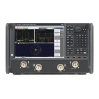
1. 67 GHz PNA with congurable test set or PNA-X network analyzer
2. Either a N5261A (2-port) or N5262A (4-port) millimeter-wave test set controller
3. A set of N5250CX10 67 GHz to 110 GHz frequency extenders
The following table provides a list of available system components that may be selected to create a 10 MHz to 110 GHz solution.
Product/ options Description
67 GHz PNA-X/PNA network analyzer1
N5227A -201/ 219 or
N5247A -200
2-ports, single source 10 MHz to 67 GHz PNA-X or PNA with congurable test set
N5227A-401/ 419 or
N5247A-400
4-ports, dual source PNA-X or PNA with congurable test set
N5227A -020
N5247A -020 Required
Adds rear panel direct access IF Inputs for either N5227A or N5247A
2
2-port millimeter wave test set controller3
N5261A 2-port millimeter-wave test set controller for PNA/ PNA-X based conguration
N5261A-112, required A set of cables for 1.85 mm connection to a 2-port PNA/ PNA-X N5247A
Must choose one of the following connection cables. One per module.
N5261A-501 A single set (1-port) of RF,LO,DC and IF cables for connection to a single T/R millimeter module, 48"
N5261A-502 A single set (1-port) of RF,LO,DC and IF cables for connection to a single T/R millimeter module, 2 meter
N5261A-503 A single set (1-port) of RF,LO,DC and IF cables for connection to a single T/R millimeter module, 3 meter
N5261A-505 A single set (1-port) of RF,LO,DC and IF cables for connection to a single T/R millimeter module, 5 meter
4
4-port millimeter wave test set controller3
N5262A 4-port millimeter-wave test set controller for PNA/ PNA-X based conguration
N5262A-114, required A set of cables for 1.85 mm connection to a 4-port PNA/ PNA-X N5247A
Must choose one of the following connection cables. One per module.
N5262A-501 A single set of RF,LO,DC and IF cables for connection to a single T/R millimeter module, 48"
N5262A-502 A single set of RF,LO,DC and IF cables for connection to a single T/R millimeter module, 2 meter
N5262A-503 A single set of RF,LO,DC and IF cables for connection to a single T/R millimeter module, 3 meter
N5262A-505 A single set of RF,LO,DC and IF cables for connection to a single T/R millimeter module, 5 meter
4
Millimeter-wave frequency extenders
N5250CX10-L05 67 to 110 GHz, left T/R module & 1.00 mm combiner assembly without adjustable attenuator, or bias tee
N5250CX10-L10 67 to 110 GHz, left T/R module & 1.00 mm combiner assembly with adjustable attenuator, and no bias tee
N5250CX10-L15 67 to 110 GHz, left T/R module & 1.00 mm combiner assembly with bias tee, and no adjustable attenuator
N5250CX10-L20 67 to 110 GHz, left T/R module & 1.00 mm combiner assembly with adjustable attenuator and bias tee
N5250CX10-R10 67 to 110 GHz, right T/R module & 1.00 mm combiner assembly without adjustable attenuator, or bias tee
N5250CX10-R15 67 to 110 GHz, right T/R module & 1.00 mm combiner assembly with adjustable attenuator, and no bias tee
N5250CX10-R20 67 to 110 GHz, right T/R module & 1.00 mm combiner assembly with bias tee and no adjustable attenuator
N5250CX10-R30 67 to 110 GHz, right T/R module & 1.00 mm combiner assembly with adjustable attenuator and bias tee
N5227A PNA or N5247A PNA-X based single sweep solution hardware conguration table
Notes
1. For PNA/PNA-X options select either a 2-port option for a 2-port 110 GHz conguration or a 4-port option for 4-port 110 GHz solutions.
2. Option 020 is a required option that allows for direct connection of the IF into the back of the PNA/PNA-X.
3. The millimeter-wave test set controller will include cables and the lock link kit to interface to the PNA/PNA-X when either Option 112 or 114 is selected.
4. When selecting Option 505, cable set external RF and LO ampliers will be required because of cable loss around 6.6 dB.
5. The Kelvin bias-tees have a voltage rating of 40 volts and a maximum of 0.5 amps.
Broadband Solution Conguration
12 | Keysight | Antenna Test – Selection Guide

 Loading...


