Pulse measurements (Option 008)
1
The PNA receiver has optional Pulse measurement capability (Option 008). This option
provides software to set up and control pulsed-RF measurements with point-in-pulse and
pulse-prole capability.
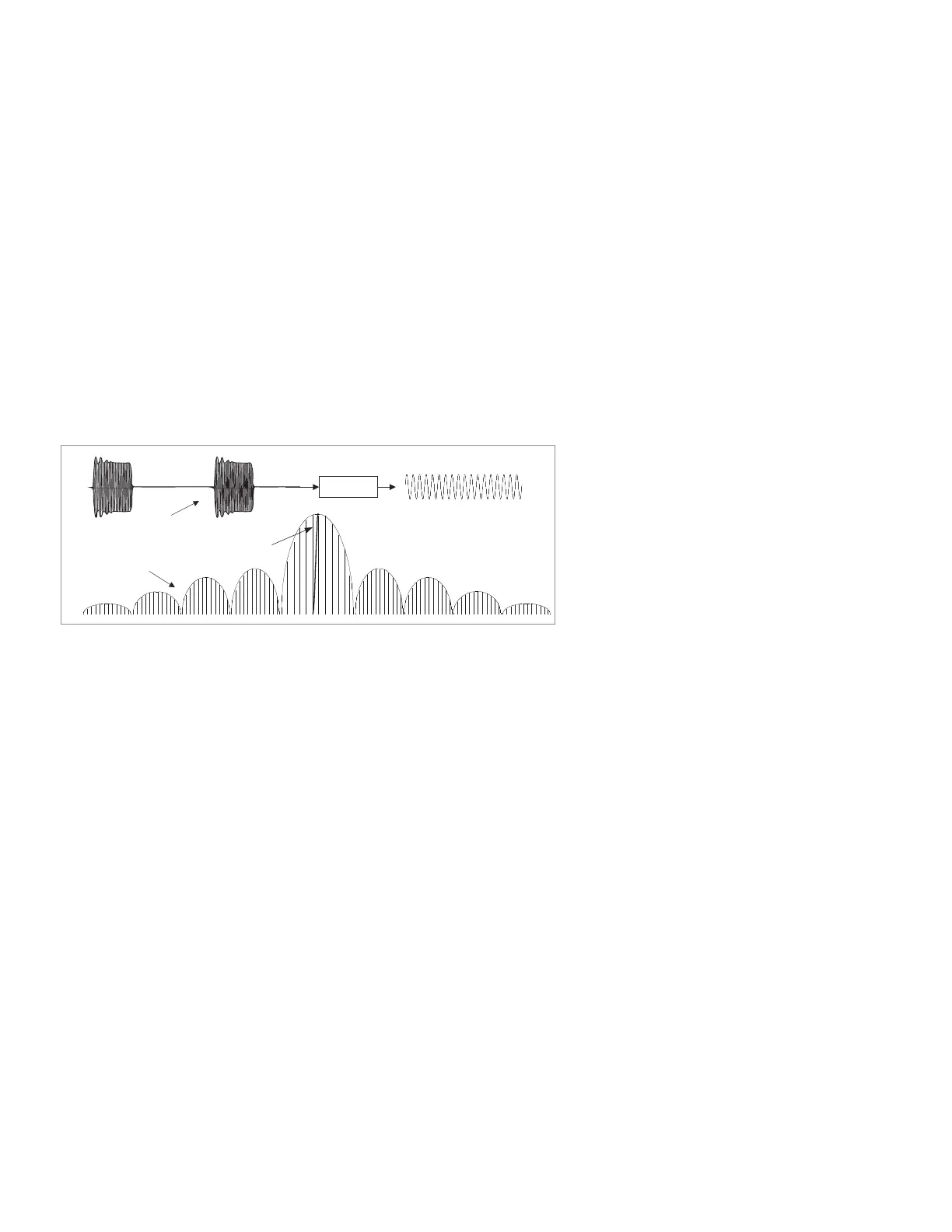
Keysight has developed a novel way of achieving narrowband detection using wider IF
bandwidths than normal, by using a unique “spectral-nulling” technique that lets the user
trade dynamic range for speed, with the result almost always yielding faster measurements
than those obtained by conventional ltering. The advantage to narrowband detection is
that there is no lower pulse-width limit, since no matter how broad the pulse spectrum
is, most of it is ltered away anyway, leaving only the central spectral component. The
disadvantage to narrowband detection is that measurement dynamic range is a function
of duty cycle. As the duty cycle of the pulses gets smaller (longer time between pulses),
the average power of the pulses gets smaller, resulting in less signal-to-noise ratio. In this
way, measurement dynamic range decreases as duty cycle decreases. This phenomenon
is often called “pulse desensitization”. The degradation in dynamic range (in dB) can be
expressed as 20*log (duty cycle).
Figure 35. Time domain.
The IF gates supplied with Option H11 can only be used with Option 008. 008 includes all
of the proprietary algorithms necessary to implement the spectral nulling technique used
with narrowband detection. 008 also controls the pulse generator(s) used in the system,
and performs pulse-prole measurements. Option 008 comes with two software com-
ponents. One is a dynamic-link library (DLL) which acts as a “sub-routine”, and is needed
for automated environments. The second portion is a Visual Basic (VB) application that
runs on the PNA. This VB application is used for stand-alone, bench-top use. It interacts
with the DLL and sends appropriate commands to the PNA and the pulse generator(s).
The VB application is assigned to one of the PNA’s macro keys for easy access.
See Table 1 in section 3 for a list of PNA Series network analyzers, their frequency
ranges, power and sensitivity. Refer to the PNA data sheet for additional specications,
literature number 5988-7988EN.
For more detailed information regarding pulsed measurement capabilities with the mi-
crowave PNA refer to the Keysight Web site www.keysight.com/nd/pna and download
the PNA Series MW Network Analyzers Conguration Guide for Pulsed Measurements,
literature number 5988-9833EN. Additional information is also available in Application
Note 1408-11, literature number 5989-0563EN, and Pulsed Antenna Measurements Us-
ing PNA Network Analyzers, literature number 5989-0221EN.
1. Up to 67 GHz.
IF filter
IF filter
Time domain
Frequency domain
D/R degradation = 20*log[duty cycle]
51 | Keysight | Antenna Test – Selection Guide

 Loading...


