Chapter 1: Installation and wiring
P/N 3102351-EN • REV 005 • ISS 28DEC18 13
Circuit specifications
• Class B, Class A, or Class X
• Communication line voltage: Maximum 20.6 V peak-to-peak
• Circuit current: 0.5 A max.
• Allowable circuit resistance: 66 Ω max.
• Allowable circuit capacitance: 0.5 µF max.
• Resistance between isolators: Limited only by overall wire run lengths
• Isolators: 64 maximum per loop (total both isolator bases and modules)
• Ground fault impedance: 0 to 5 kΩ
• Power-limited and supervised
• Synchronization: Signal synchronization is supported on a system-wide basis (all device
loops) when using CC1S, MCC1S, or T3T4 addressable notification appliance circuit (NAC)
modules and Genesis or Enhanced Integrity notification appliances.
Installation limits are subject to acceptance by the AHJ.
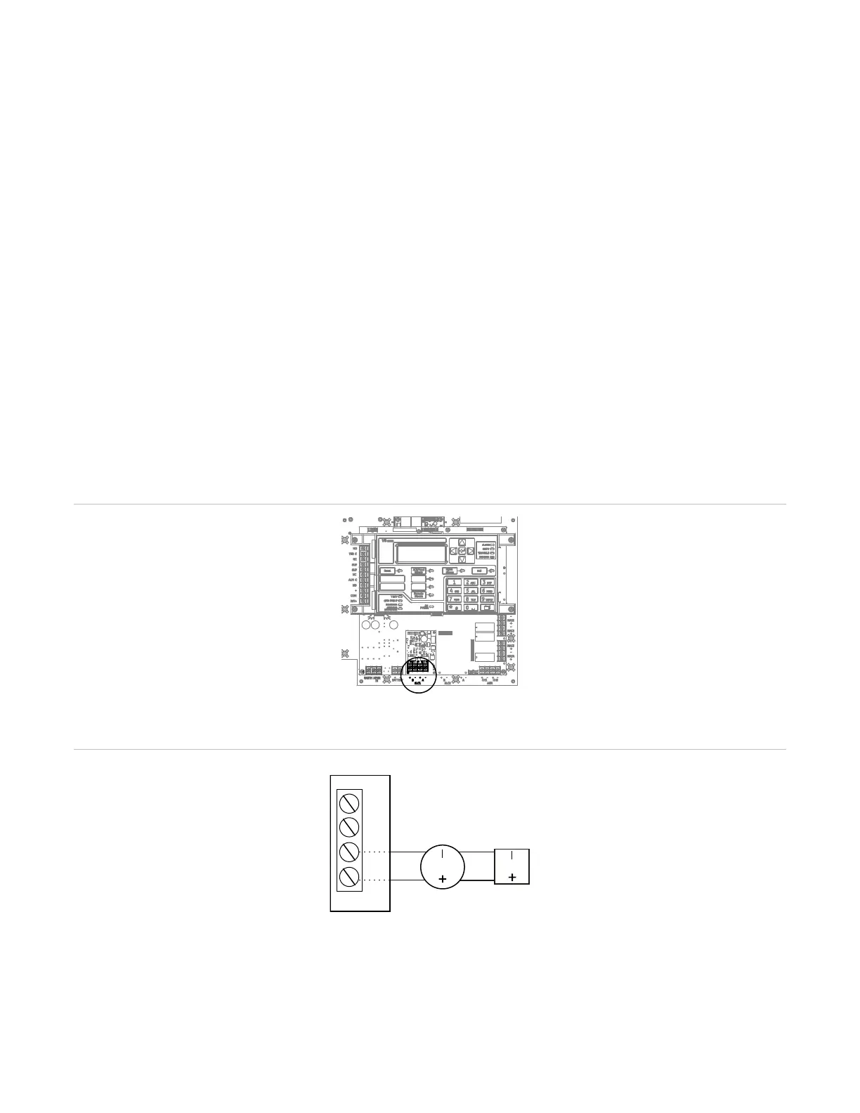
Figure 14: Device loop wiring location
Figure 15: Class B wiring