Appendix C: Applications
P/N 3102351-EN • REV 005 • ISS 28DEC18 223
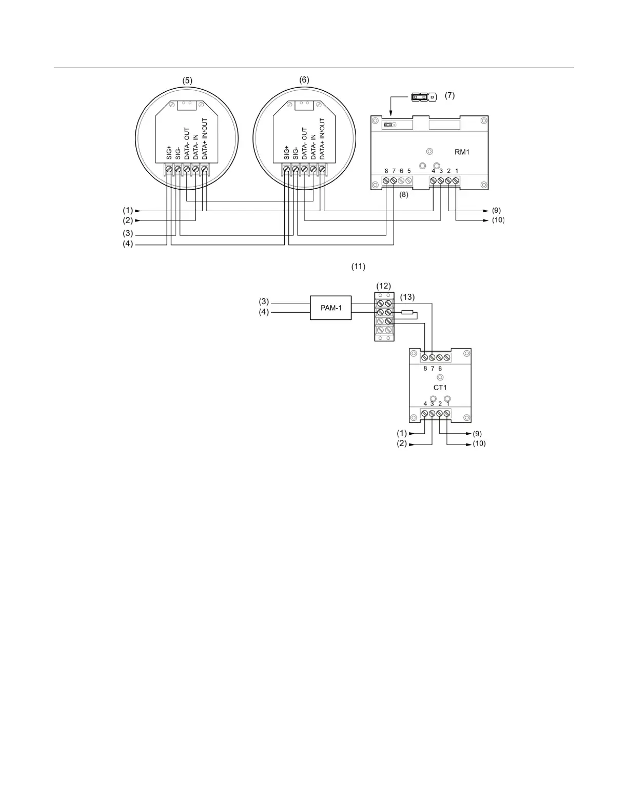
Figure 57: Typical wiring for a local alarm signaling application
2) SLC IN −
AUX riser 24 VDC +
AUX riser 24 VDC −
First detector
Last detector
(9) SLC OUT +
(10) SLC OUT −
(11) Alternate riser supervision circuit
(12) Double screw terminal block
(customer supplied)
Programming sounder bases for a local alarm signaling
application
Note: For PS/PD, PHS/PHD, IPHS, and SD detectors configured as “Supervisory Non-
latching” device type or for PCOS/PCD detectors (smoke element) configured as “Smoke
Supervisory Non-latching” device type, if the base is Relay/Sounder, then the follow type
option cannot be configured as “Head.” The follow type in this case should be set to “Alarm.”
1. Set the panel’s Event Notification option to Device.
2. Configure the smoke detectors as follows:
Device Type: Smoke or Smoke Heat depending on the detector model