TOS7200 7
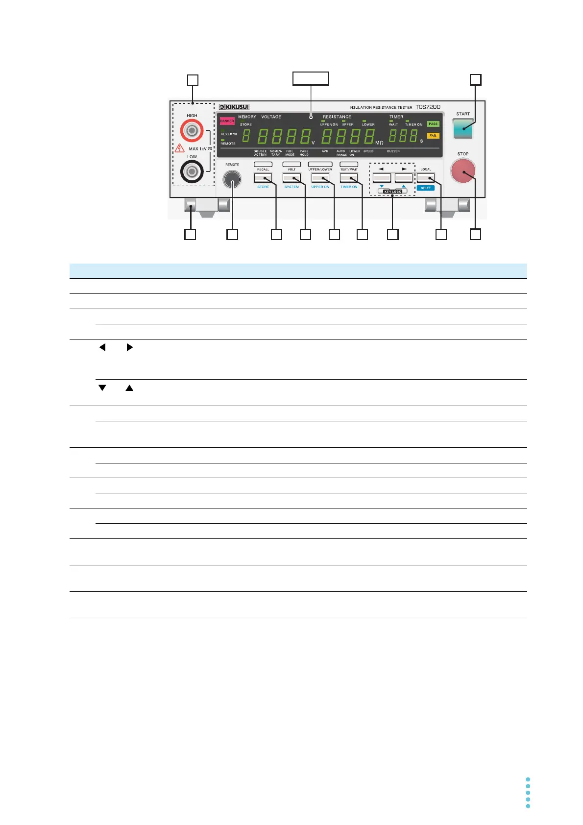
Front Panel
MEMORY
VOLTAGE
RESISTANCE
TIMER
MEMORY VOLTAGE RESISTANCE TIMER
OUTPUT
2
3456789
11
No. Name Description See
1 START switch Starts testing. p. 30
2 STOP switch Stops testing and clears the current status. Cancels a PASS or FAIL judgment. p. 31
3 LOCAL key Switches RS232C remote mode (REMOTE LED lit) to local mode. —
SHIFT key Used to access the features that are written in blue. —
4
and keys
Moves the cursor when setting test conditions or the like.
*1
Pressing them both at the same time locks the keys and turns on the KEYLOCK
LED.
—
and keys
Increases or decreases the numerical value of the digit at which the cursor is
located.
—
5 TEST/WAIT key Sets the test duration or wait time. p. 28
TIMER ON key Switches between ON and OFF for the test-duration timer function (TIMER ON
LED).
p. 28
6 UPPER/LOWER key Sets the upper or lower resistance p. 24
UPPER ON key Switches between ON and OFF for the upper judgment p. 27
7 VOLT key Sets the test voltage p. 23
SYSTEM key Switches to the system setting display. p. 33
8 RECALL key Recalls panel settings from memory p. 36
STORE key Stores panel settings to memory p. 36
9 REMOTE terminal This dedicated terminal is used to connect the optional remote control box
RC01-TOS or RC02-TOS.
p. 40
10 OUTPUT terminal Test voltage output terminals
Connected in parallel with the OUTPUT terminals on the rear panel.
p. 16
11 Legs These legs are provided to raise the front part of the tester to make it easier to
view the front panel screen and operate the keys.
p. 4
*1. The location of the cursor is indicated by a blinking 7-segment LED on the display unit. This blinking will stop if no
keystroke is entered for 5 seconds or more.