1. INTRODUCTION
1.1. Description of the transmitter
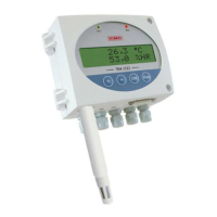
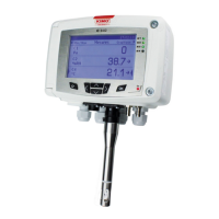
Class 210-R transmitters with display can be configured via keypad. It is possible to set measurement units, activate or not
a channel, etc.
Principle: the configuration options are accessed via folders and sub-folders. Access is made via a numerical code
(full details in this manual).
Trend indicator: on the screen, a trend indicator represented by a rising arrow, a going down arrow or a stable arrow is
displayed above the measurement unit. It means the calculation of a moving average on the last hour (M1) to compare
with a moving average on the last 5 minutes (M2):
• If M1 = M2, the trend is stable.
• If M1 < M2, the trend is upwards.
• If M1 > M2, the trend is downwards.
Indicator light: the indicator light blinks quickly during the initialisation phase of the transmitter then becomes fixed
when this phase has been completed.
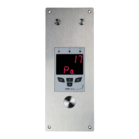
For the pressure transmitters with solenoid valve (CP211-R and CP212-R), it blinks when the solenoid valve is activated.
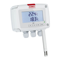
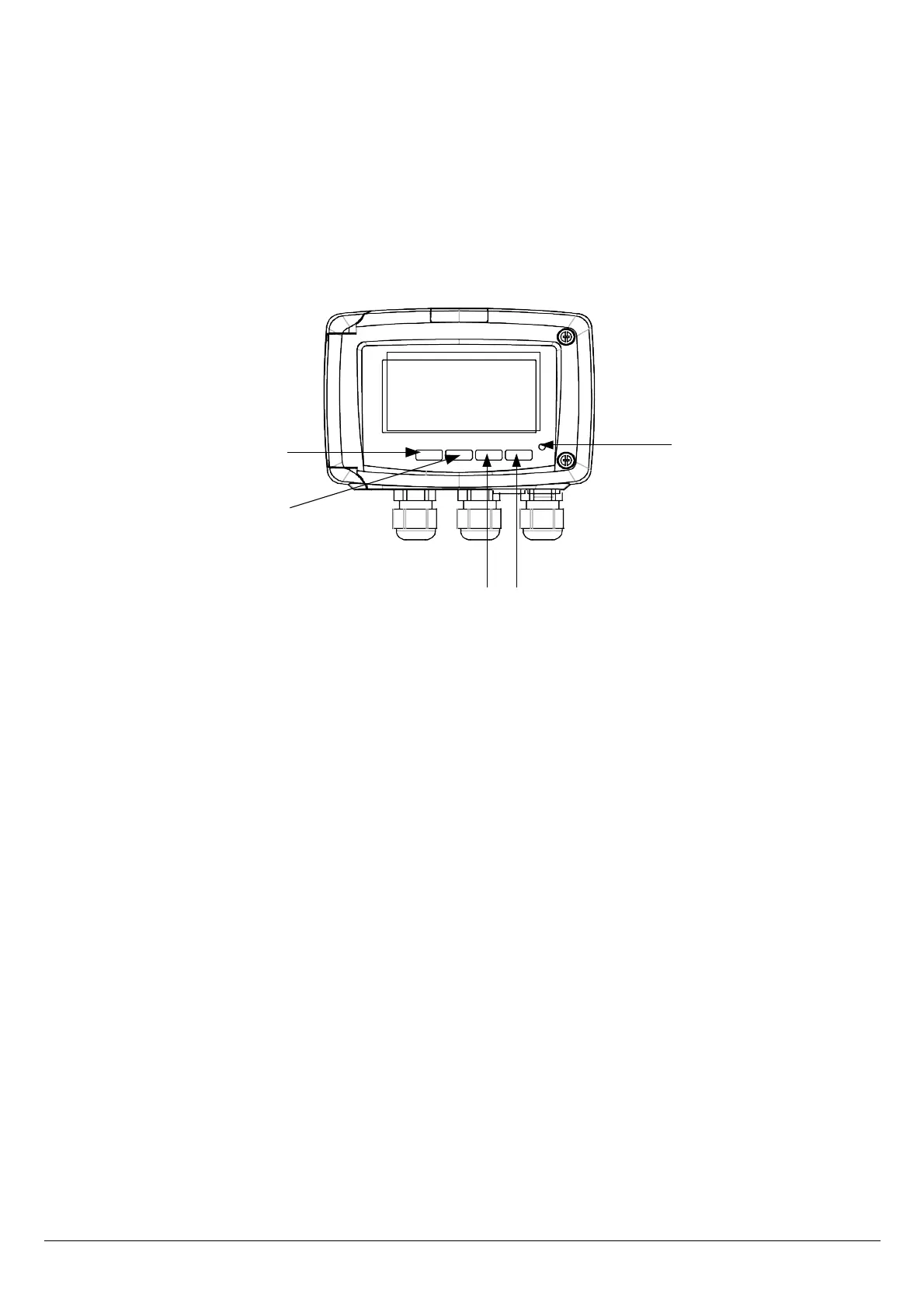
1.2. Description of the keys
– Up key: increments a value or a level
– Down key: decrements a value or a level
– OK key: validates an input
– Esc key: cancels an input or backs to the previous step
INTRODUCTION
5
10 pa
Up key
Down key
OK key Esc key
Indicator light
 Loading...