2. WARNING
2.1. Wiring
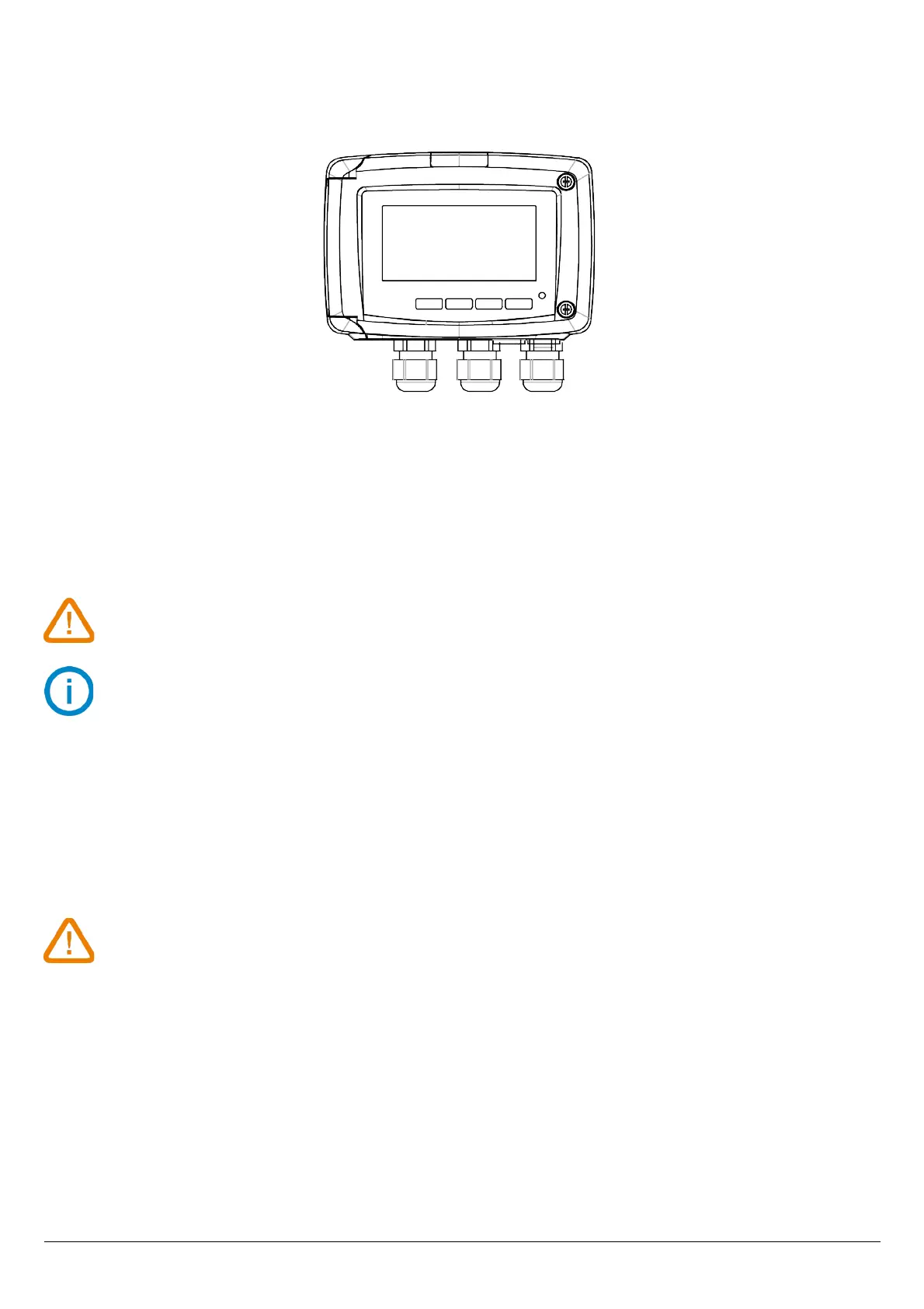
In order to avoid cross-wiring:
• 1: this cable-gland must be reserved to relays
• 2: this cable-gland must be reserved to analogue outputs
• 3: this cable-gland must be reserved to power supply
To consider cable-glands as fixation points, the cable diameter range to place in the cable gland
must be between 4 and 8 mm.
The power supply wiring must be performed with crimping copper connections or a tinning in case
of multi-wire cable.
➢ After performing the wiring, tight the cable-glands.
For details about the different wiring possibilities, please see the data sheet of the concerned sensor.
2.2. Probes
To avoid any device damage, probes must not be subject to voltage above 30 Vac or 60 Vdc with
respect to the ground.
WARNING
7
1 32
 Loading...