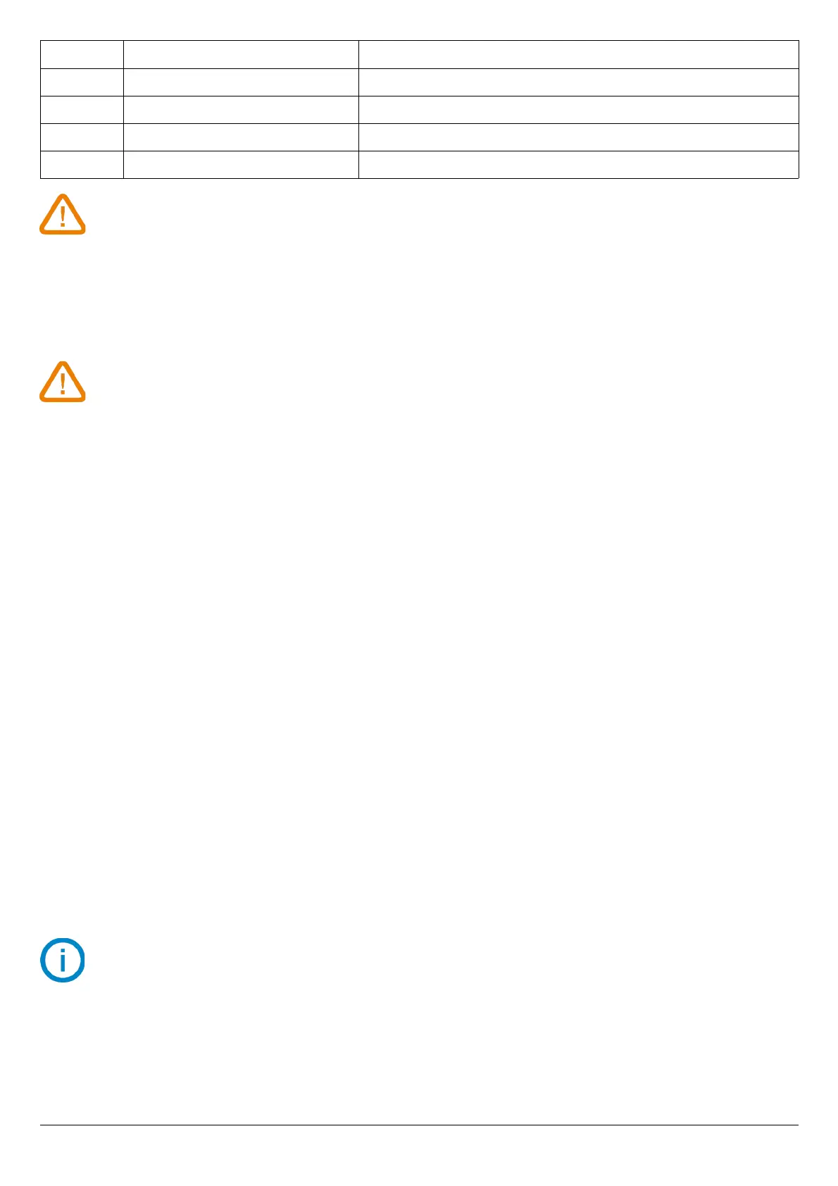
Screen Generated output Example
0 Deactivated -
1 Simulates 0% of the output range On the 0-10V range, the transmitter will generate 0V.
2 Simulates 50% of the output range On the 0-10V range, the transmitter will generate 5V.
3 Simulates 100% of the output range On the 0-10V range, the transmitter will generate 10V.
If the deviations are too large (> 0.05V or > 0.05mA) between the signal issued and the value
displayed on the multimeter, we recommend to return the transmitter to our factory.
➢ For the diagnostic of the channel 2, go to “F 311” folder and do the same procedure as the channel 1.
6.2. Set the range of the analogue outputs
This function allows to modify the range of the analogue outputs.
Values to enter depend on the measurement unit and not on the measurement range of the
transmitter.
Ex: on a CP211-R pressure transmitter (0 to ±1000 Pa) with a reading in mmH
2
O, the minimum and maximum ranges must
be configured on measuring range of 0 to ±102 mmH
2
O. See conversion chart on page 15.
The transmitter is powered on.
➢ Press OK.
➢ Enter the activation code (see page 8).
➢ Press OK.
➢ Press Up key to go to folder “F 302” corresponding to the low range of the channel 1.
➢ Press OK.
The first digit of the low range blinks.
➢ Enter with Up and Down keys the figure value or the negative sign of the value then press OK.
The second digit blinks.
➢ Enter with Up and Down keys its value then press OK.
➢ Perform the same procedure for the following figures.
➢ Press OK when the last figure has been configured.
“F 302” blinks, the low range is configured.
➢ Press Up key then press OK to enter in the folder “F 303” corresponding to the high range of the channel 1.
The first digit of the high range blinks.
➢ Enter with Up and Down keys the figure value or the negative sign of the value then press OK.
The second digit blinks.
➢ Enter with Up and Down keys its value then press OK.
➢ Perform the same procedure for the following figures.
➢ Press OK when the last figure has been configured.
“F 303” blinks, the high range is configured.
To set the low and high ranges of the channel 2, go to the folders “F 312” (low range) and “F 313”
(high range) and follow the setting procedure of the channel 1.
F 300: ANALOGUE OUTPUTS MANAGEMENT
13
 Loading...