TM
Model 3600M0259-01
Rev. 9/17 2-21
Machine Operation
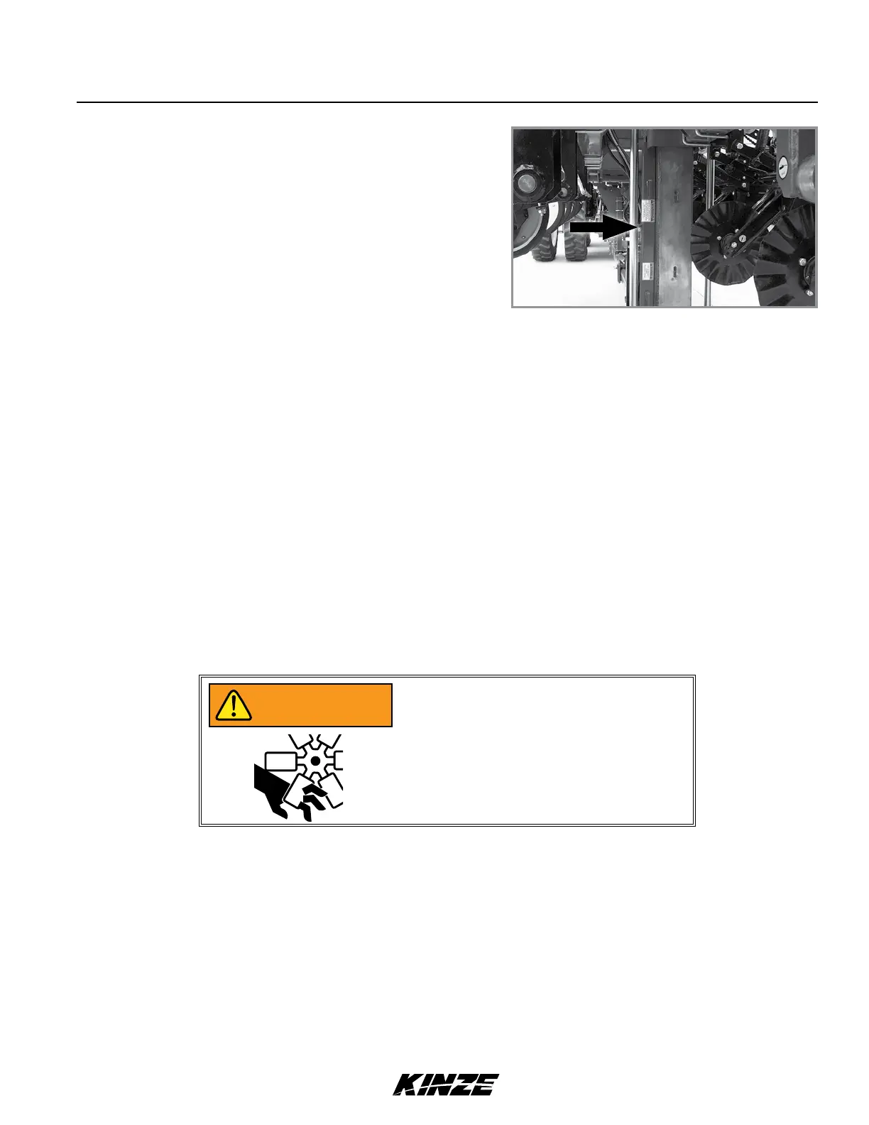
VACUUM FAN MOTOR VALVE BLOCK ASSEMBLY
A pressure relief valve in the hydraulic circuit prevents build up of oil pressure over 35 PSI in case drain line when
vacuum fan motor is operating. This valve will vent oil outside valve block through a drain hole in the aluminum valve
block. This can occur whenever case drain is improperly connected or pressure in motor circuit builds.
See “Hydraulic Diagram - Vacuum Fan Motor System” in Maintenance section.
Valve block contains a check valve that prevents vacuum fan from operating in wrong direction if pressure is applied to
return side of motor and allows fan to coast to a stop when tractor hydraulic control is returned to neutral position.
NOTE: Fan turns at a reduced speed If reverse pressure is applied.
DIGITAL VACUUM READOUT
Digital vacuum readout is incorporated into in-cab display. Refer to the display operation manual for instructions.
Kinze vacuum meter seed metering system includes seed meters, seed discs, and an air system consisting of a
hydraulic driven vacuum fan which draws air through manifolds, hoses, and seed meters on each row unit.
VACUUM METER SYSTEM
10. Remove manual safety lockup from storage location on left
side of axle assembly and position it behind front center lift
cylinder.
Manual safety lockup installed
Moving fan blades can cause amputation
or severe injury. Never operate vacuum
fan with cover removed.
WARNING