THREE-POINT HITCH & DRAWBAR 8-3
196O803A196O802A
3-POINT HITCH
MAKE PREPARATIONS FOR
ATTACHING IMPLEMENT
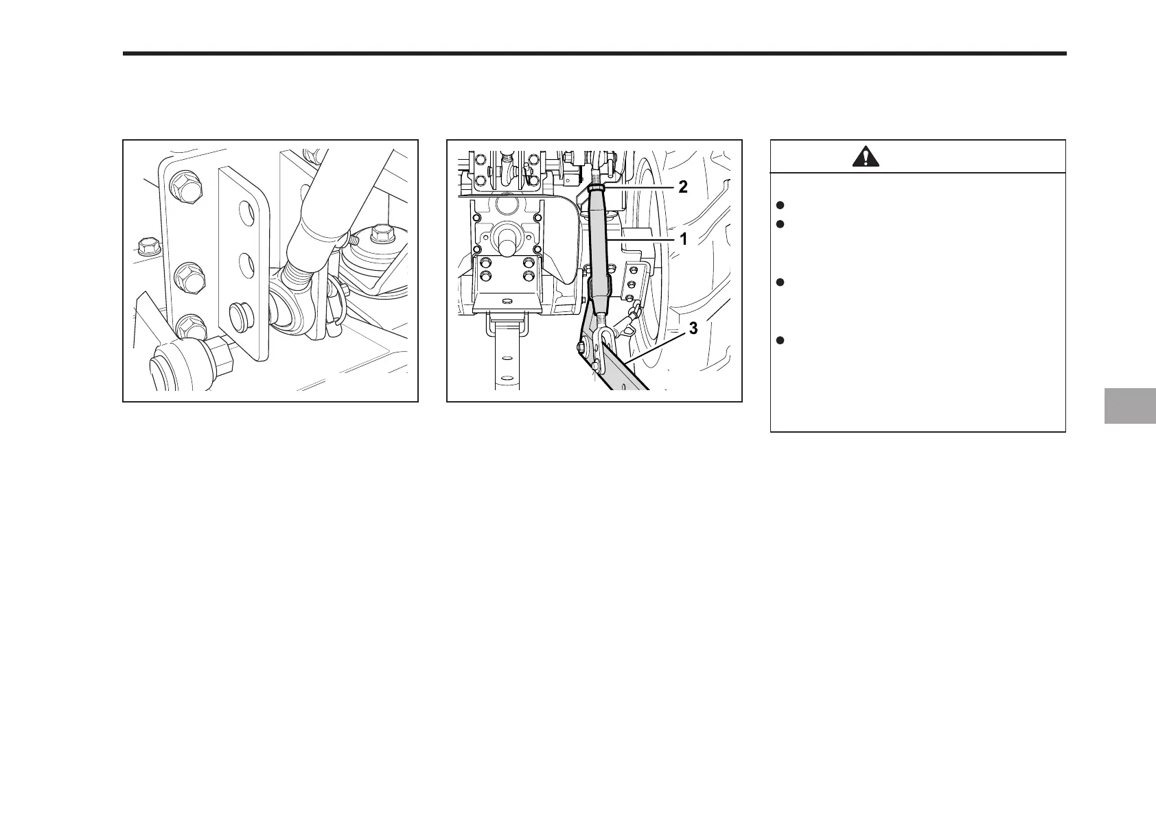
SELECTING THE TOP LINK MOUNTING
HOLES
Select the proper set of holes by refer-
ring to the “Hydraulic Control Unit Use
Reference Chart” in Hydraulic Unit
section.
DRAWBAR
Remove the drawbar if close mounted
implement is being attached.
ATTACHING AND DETACHING
IMPLEMENTS
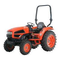
(1) Lifting Rod (Right) (3) Lower Linle
(2) Nut
LIFTING ROD (RIGHT)
Lift Rod - To adjust the horizontal posi-
tion of the implement twist the turn buckle
on the right lift rod. Most implements are
designed to operate level. Set the posi-
tion desired by tightening the set nut
against the turn buckle.
TOP LINK
1. Adjust the angle of the implement to
the desired position by shortening or
lengthening the top link.
2. The proper length of the top link varies
according to the type of implement
being used.
CAUTION
To avoid personal injury:
Be sure to stop the engine.
Do not stand between tractor and
implement unless parking brake
is applied.
Before attaching or detaching
implement, locate the tractor and
implement on a firm level surface.
Whenever an implement or other
attachment is connected to the
tractor 3-point hitch, check full
range of operation for interference,
binding or P.T.O separation.