9-4 CK20
196O905A
196O904A
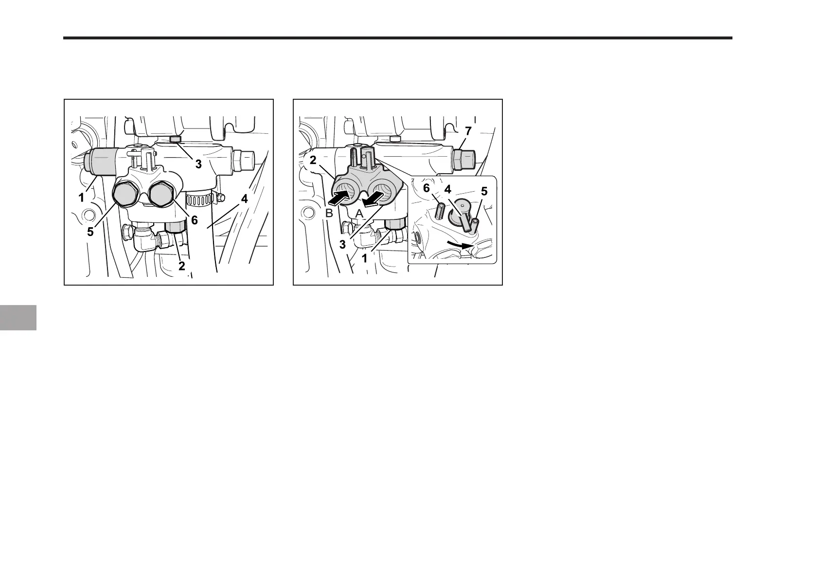
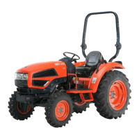
(1) Flow Priority Valve
(2) Inlet from Implements (PS 3/8´´)
(3) Outlet to Implements (PS 3/8´´)
(4) Directional Valve
(5) Pin (Setting Position for Attaching
Implements)
(6) Pin (Setting Position for Attaching no
Implement)
(7) Relief Valve
(A) Out (B) In
The main components of the hydraulic
block outlet are shown in the figure. The
hydraulic block outlet is used to take
power out from the tractor to operate the
implements that require hydraulic
pressure.
When implement is not attached When implement is attached
(1) To Hydraulic Control Valve (3-point hitch)
(2) To Power steering (PS type only)
(3) From Gear Pump
(4) To Gear Pump (Relief Valve)
(5) From Implement
(6) To Implement