OPERATION 5-21
WARNING
When leaving the driver’s seat to
attach or detach implements:
Shift the transmission into
neutral.
Set the parking brake.
Slow the engine to idle speed.
Push the draft control lever for-
ward to the floating range.
Keep bystanders clear of the trac-
tor and the implement.
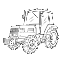
1. Adjust the position (leveling) of the
implement by turning the lift linkage lo-
cated on the right side.
2. After the adjustment, secure with the
lock nut.
3. Positioning is dependent upon the type
of implement.
LEVELING ADJUSTMENT (MANUAL)
C86O529A
(1) Lift Linkage
The lift can be controlled from the ground
while attaching or detaching implements.
EXTERNAL POSITION CONTROL LEVER
C86O530A
(1) External Position Control Lever
ADJUSTMENT OF CHECK LINK
Adjust the stabilizers to control horizon-
tal sway of the implement.
C86O528A
(1) Stabilizer (2) Pin
Type of implement
Plow, furrow,
subsoiler,
cultivator, ditcher
Rotary mower,
hay rake, tender,
ridger
Stabilizer adjust-
ment
Loosen until the
implement can be
moved 50 ~ 60 mm
(1.97 ~ 2.36 in.)
horizontally.
Tighten securely