DP405 Service Manual
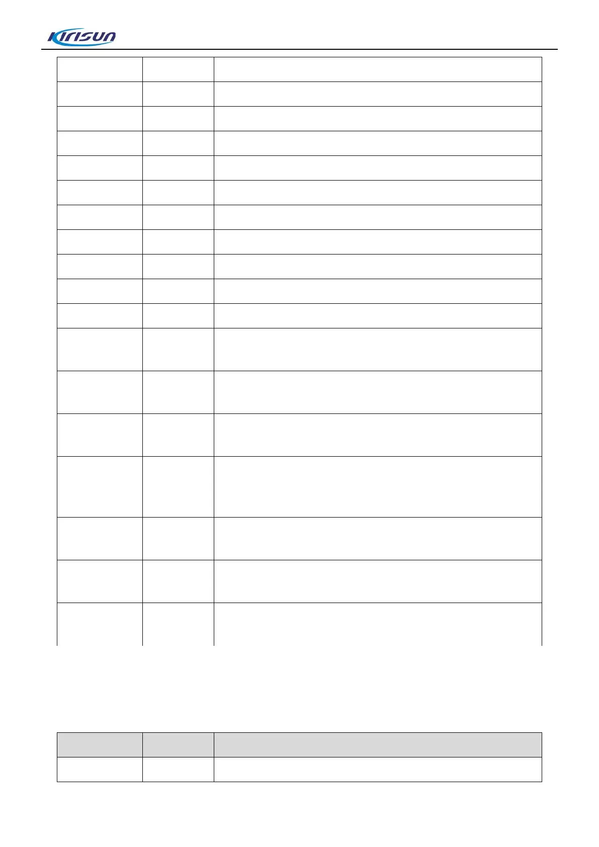
RFIN 15 RF signal input
AVDD 16 Power supply
NC* 17 No connection
RFOUT 18 RF signal output
NC* 19 No connection
NC* 20 No connection
AVDD 21 Power supply
PABIAS 22 PA bias supply for PA
AVDD 23 Power supply
PDN 24 Chip enable,high active; Chip sleep,low active
GPIO7 25 Gpio7/vox(When Gpio7=VH, vox is active; else VL)
GPIO6
26
Gpio6 / sq
(When Gpio6=VH, sq is active; else VL)
GPIO5
27
Gpio5 / txon
(When Gpio5=VH, txon is active; else VL)
GPIO4
28
Gpio4 / rxon
(When Gpio4=VH, rxon is active; else VL)
GPIO3
29
Gpio3 / sdo
(Gpio3=VH or VL, it is the output register data in 4 wire control
Interface mode)
GPIO2
30
Gpio2 / int
(When Gpio2=VH, int is active; else VL)
GPIO1
31
Gpio1 / code_in / code_out
(Gpio1=VH or VL, it is the input/output code data)
GPIO0
32
Gpio0 / css_in / css_out
(Gpio0=VH or VL, it is the input/output CTCSS/CDCSS signal)
3.7. Semiconductor Device Feature Description
Position Mark MODEL Description
IC500 NJM2904 APC,voltage comparison, drive
11

 Loading...


