DP770 Service Manual
Step1: The 1575.42MHz GPS signal is received by the antenna, and then goes to HPF to remove the
in-band signals used for transmission and reception.
Step2: The signal goes to GPS module for amplification and filtering after frequency selection via filter.
Then it will be sent to baseband section for calculation.
Step3: The calculated GPS position information is sent to OMAP for processing via the UART interface.
Meanwhile, OMAP138 can send appropriate command information to the GPS module via the UART
interface.
Step4: Finally, the OMAP sends the processed data information to the LCD.
3.2. Baseband Section
3.2.1. Power Section
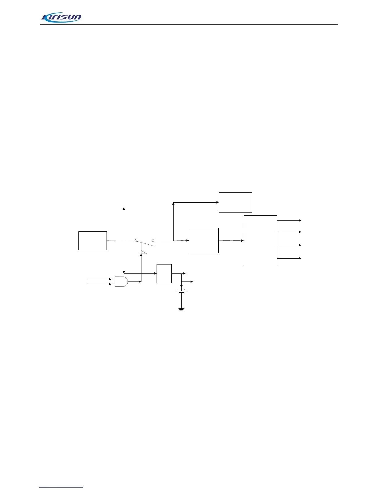
Figure 3-7 Power Section Diagram
The radio adopts 7.4V li-i
on battery as power supply. The baseband and RF circuit are supplied by
independent power structure. The baseband power is composed of two stage conversion circuit. The first
stage reduces the battery voltage to 5V by DC/DC, and the second stage converts the 5V voltage to power
required voltage for the system by the power management.
Power On/Off: Power On/Off is implemented through a PMOS component. When the Power On/Off key is
pressed, PWR_Key signal becomes high level, and PMOS component becomes conducted. The system
will begin initialization and set Soft_ctr to be high level. Thus, the radio is powered up. During the power off
process, when the system detects that the Power On/Off key is pressed, the system will begin executing
the shut down operations, and finally set Soft_ctr to be low level, which will shut down the PMOS
component, thus the radio being powered off.
3.2.2. Audio Section
The audio module is mainly for audio input and output. It uses TLV320AIC14 as audio codec to convert and