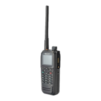
DP770 Service Manual
Step 5. Refer to Figure 5-8. Insert the flat-bladed screwdriver
into the slot of Al alloy bracket; lift it so as to separate the Zinc
alloy bracket from the chassis, and then push the Al alloy
bracket away from the chassis, and take the soft flat cable
away from the socket. Separate the speaker connecting cable
by the soldering iron to.
Fi
gure 5-8
5.5. Removing the PCB board from the Chassis
Step 1. Remove the ten screws on the PCB board.
Step 2. Cut off the antenna connecting point by the soldering iron and then separate the PCB board
from the chassis.
Figure 5-9
5.6. Detaching the Keypad Board from the Case
Step 1. Insert the flat-bladed screwdriver into the slot between the volume knob and case, lift the
volume knob and take off it. Remove the volume knob nut by special tool in the clockwise direction.
Separate the volume soft flat cable from the socket.
Figure 5-10
Step 2. Separate the speaker and MIC cable by soldering iron.
Page 20 of 102

 Loading...