DR600 Service Manual
Baseband Board Power Supply
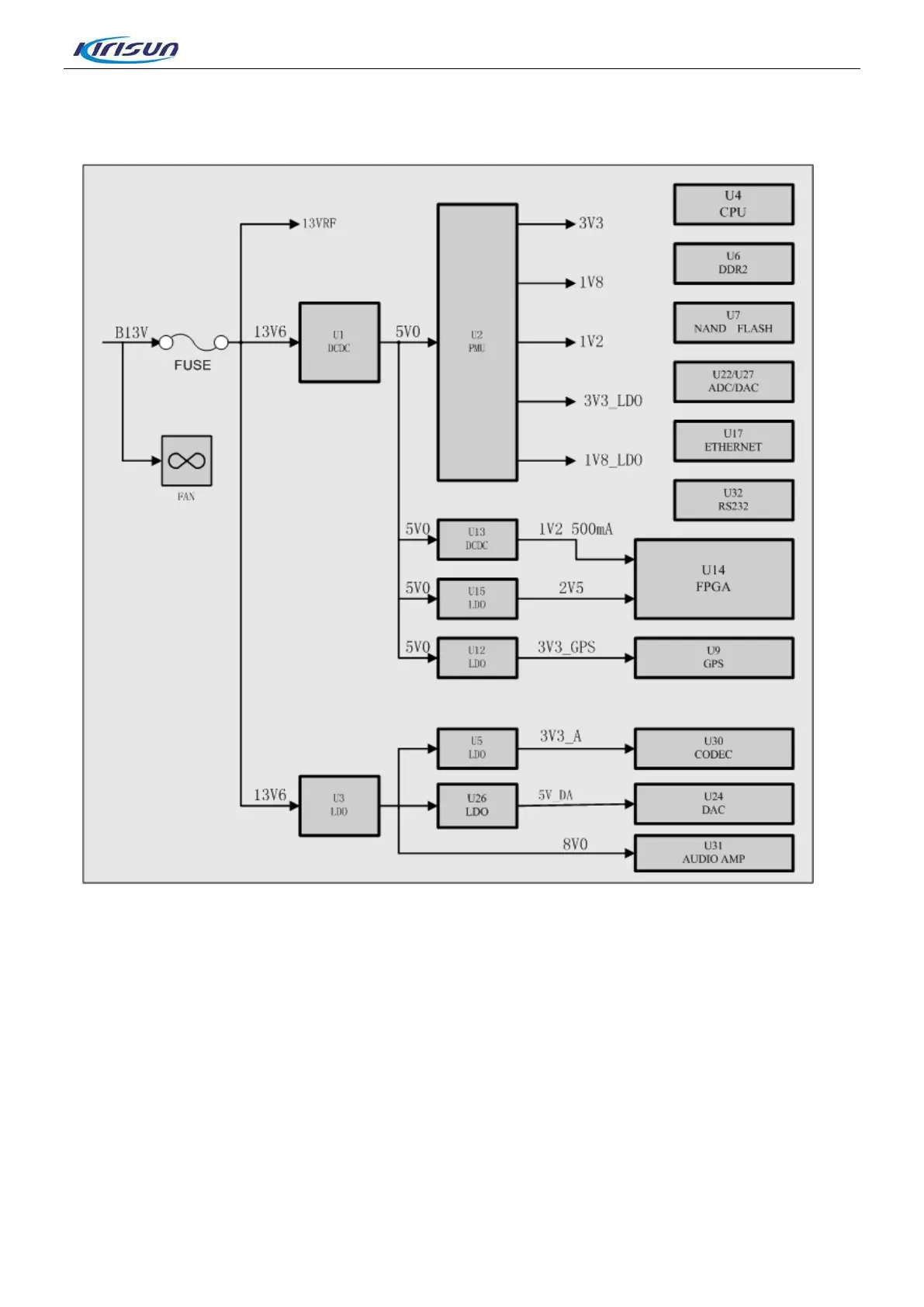
Figure 3-10 Baseband Board Power Supply Distribution Diagram
As Figure 3-10 shows, the baseband and RF employs isolated power supply. B13V will be divided into
three paths. One path provides power for baseband circuit, the second one is provided for Tx and Rx
module after being isolated by magnetic bead, and the last one is provided for heat dissipation fan after
being isolated by the ferrite Inductor.
The digital and analog part of the baseband circuit own separate power supply.
The power supply of the digital circuit is composed of two-level switch circuit. The first level decreases
the B13V to 5V via DC/DC (U1) ; the second level switches 5V to 3.3V, 1.8V, 1.2V and etc.. which are
isolated by various magnetic beads before being supplied to the circuit modules.
The analog circuit power supply will be directly supplied to analog audio power amplification circuit after
being switched to 8V via LDO. One power path outputs 5V_DA via the low voltage LDO (U26) and provide
it for the analog power of DAC(U24, U27), and the other oupts 3.3V_A via the low voltage LDO (U5) and
13

 Loading...