KIRLOSKAR CHILLERS PRIVATE LIMITED
A Kirloskar Group Company IOM-KAC-ENG - Page 9
Chapter 2 Installation
2.1. Space Requirement for Servicing
Each side of the unit must be accessible for periodic service work. Servicing needs to be done
on system components like compressor(s), shut off valves, filter drier(s) etc. Compressor(s),
compressor suction and discharge isolation valves are accessible from the side(s) of the unit.
Typical location of control panel for air-cooled chillers is shown in Fig. 2.2a. The panel has
power and control section. The power section includes the required switchgear components. The
control section includes the state of art dedicated Microprocessor ‘K-smart’ controller for the
efficient operation of the chiller. Other refrigerant controls and valves are main liquid line and
liquid injection line shut-off valves, liquid line and injection line filter driers, Electronic
expansion valve that are accessible from the back end of the unit OR from side(s) of the unit
(depending on the model).
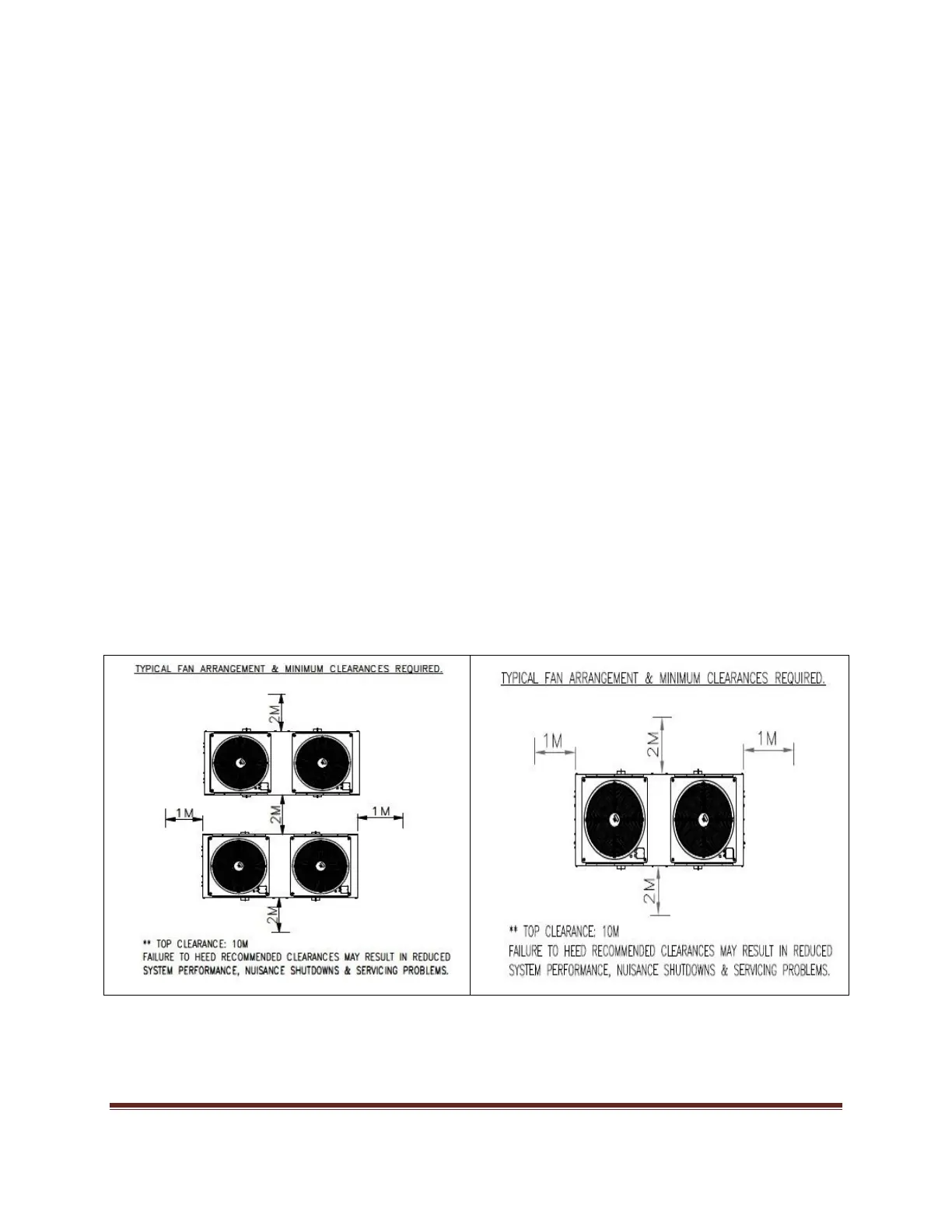
2.2. Unit Location
1. Minimum side clearance between two KAC chillers shall be 2000 mm.
2. Minimum top clearance for KAC shall be 10000 mm.
3. Over and above this, the side clearance around the chiller shall be maintained as shown in the
Fig 2.2a
Fig. 2.2a : Typical fan arrangement and minimum clearances required