EasyManua.ls Logo

KitchenAid KICU508SBL User Manual

KitchenAid KICU508SBL
40 pages
To Next Page IconTo Next Page
Page #1 background imageLoading...
Page #1 background image
TECHNICAL EDUCATION
JOB AID 4317409
KAC-47
TOUCH-ACTIVATED
ELECTRONIC
INDUCTION COOKTOP
MODELS: KICU508SBL & KICU568SBL
Question and Answer IconNeed help?

Do you have a question about the KitchenAid KICU508SBL and is the answer not in the manual?

KitchenAid KICU508SBL Specifications

General IconGeneral
BrandKitchenAid
ModelKICU508SBL
CategoryCooktop
LanguageEnglish

Summary

GENERAL

COOKTOP SAFETY

Explains essential safety precautions for using the cooktop.

MODEL & SERIAL NUMBER DESIGNATIONS

MODEL & SERIAL NUMBER LABEL AND WIRING DIAGRAM LOCATIONS

SPECIFICATIONS

INSTALLATION INFORMATION

INSTALL HEAT SHIELD

Instructions for installing the heat shield onto the cooktop.

INSTALL COOKTOP

Steps for placing and securing the cooktop into its cutout.

MAKE ELECTRICAL CONNECTION

4-Wire Cable from Home Power Supply

Guidance for connecting the cooktop using a 4-wire power cable.

3-Wire Cable from Home Power Supply

PRODUCT OPERATION

Principles Of Induction Heating

Explains the underlying technology and process of induction heating.

Advantages Of Induction Heating

Highlights benefits like faster heating, efficiency, and precision.

NORMAL OPERATION NOISES AND COOKWARE

Noises Common to Induction Cooktops

Describes typical sounds experienced during normal operation of induction cooktops.

Induction Cookware Overview

Details cookware suitability, listing good and unsuitable options.

TROUBLESHOOTING

Common Operation Problems

Addresses common issues like non-operation, overheating, and poor cooking results.

Display Errors and Messages

Interpreting and resolving issues indicated by display messages and codes.

Specific Display Error Codes

Operational Cooktop Sounds

COMPONENT ACCESS

COMPONENT LOCATIONS

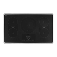
Identifies the physical locations of key internal components.

REMOVING THE COOKTOP GLASS

REMOVING THE TOUCH CONTROL BOARD

REMOVING AN INDUCTION ELEMENT ASSEMBLY

REMOVING A NEGATIVE TEMPERATURE COEFFICIENT (NTC) SENSOR

REMOVING A COOLING FAN AND AN ELECTRONIC BOARD

REMOVING A 20A LINE FUSE

COMPONENT TESTING

INDUCTION ELEMENTS

Testing procedures and resistance values for induction elements.

NEGATIVE TEMPERATURE COEFFICIENT (NTC) SENSOR

ELECTRONIC BOARD IC CHECK

20A LINE FUSES

DIAGNOSTICS & TROUBLESHOOTING

ELECTRONIC BOARD ERROR CODES

List and explanation of error codes related to electronic boards.

TOUCH CONTROL BOARD ERROR CODES

WIRING DIAGRAMS

30" COOKTOP

Schematic diagram for the 30-inch induction cooktop.

36" COOKTOP

PRODUCT SPECIFICATIONS AND WARRANTY INFORMATION SOURCES

Related product manuals