2-3
MAKE ELECTRICAL CONNECTION
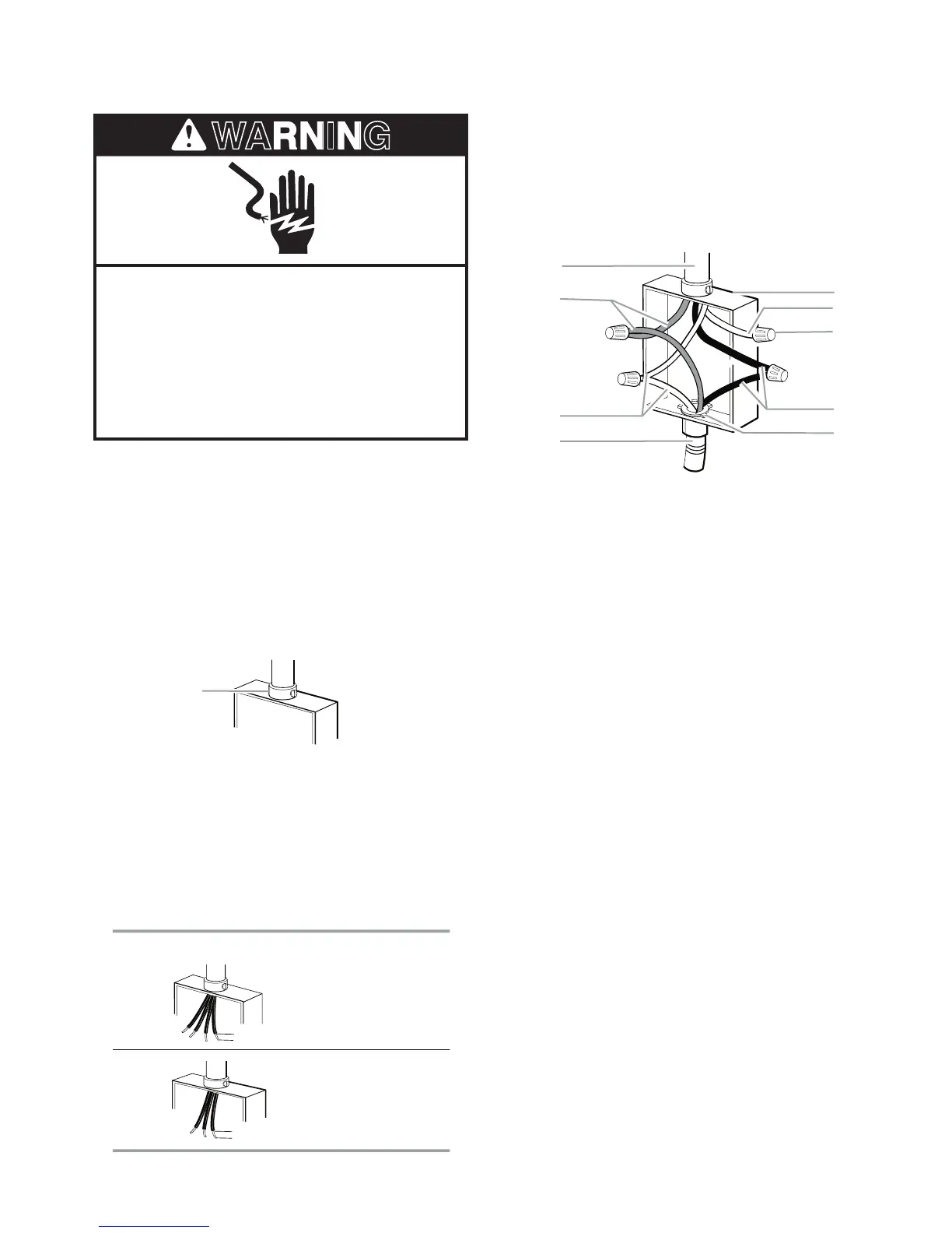
Electrical Shock Hazard
Disconnect power before servicing.
Use 8 gauge copper wire.
Electrically ground cooktop.
Failure to follow these instructions can
result in death, fire, or electrical shock.
This cooktop is manufactured with a frame-con-
n
ected, green (or bare) ground wire.
1. Disconnect power.
2. Remove junction box cover if it is pres-
e
nt.
3. Connect the flexible cable conduit from the
cooktop to the junction box using a UL listed
or CSA approved conduit connector.
4-Wire Cable from Home Power Supply
IMPORTANT: Use the 4-wire cable from home
power supply in the U.S. where local codes do
not allow grounding through neutral, New Branch
circuit installations (1996 NEC), mobile homes
and recreational vehicles, new construction,
and in Canada.
4. Tighten screws on conduit connector if
present.
5. See “Electrical Connection Options Chart”
to complete installation for your type of
electrical connection.
Electrical Connection Options Chart
. UL listed or CSA approved conduit connecto
If your home has: Go to Section:
4-wire 4-Wire Cable from
Home
Power Supply
3-wire 3-Wire Cable from
Home
Power Supply
½"
(1.3 cm)
½"
(1.3 cm)
A. Cable from home power
supply
B. R
ed wires
C. Green (or b
are) ground wire
(from cooktop)
D. 3-Wire cable from cooktop
E
. Junction box
F
. White wire (from home
pow
er supply)
G. UL listed wire connector
H
. Black wires
I. U
L listed or CSA approved
conduit connector w
ith
wire bushing
A
B
C
D
E
F
H
G
I
1. Connect the two red wires (B) together
using a UL listed wire connector.
2. Connect the green (or bare) ground wire
(C) from the cooktop cable to the green
(or bare) ground wire (in the junction box)
using a UL listed wire connector.
3. Put a UL listed wire connector on the end
of the white wire (F).
NOTE: Do not connect the green (or bare)
ground wire to the neutral (white) wire in
the junction box.
4. Connect the two black wires (H) together
using a UL listed wire connector.
5. Install junction box cover.