Front panel
12 Square ONE Dynamics
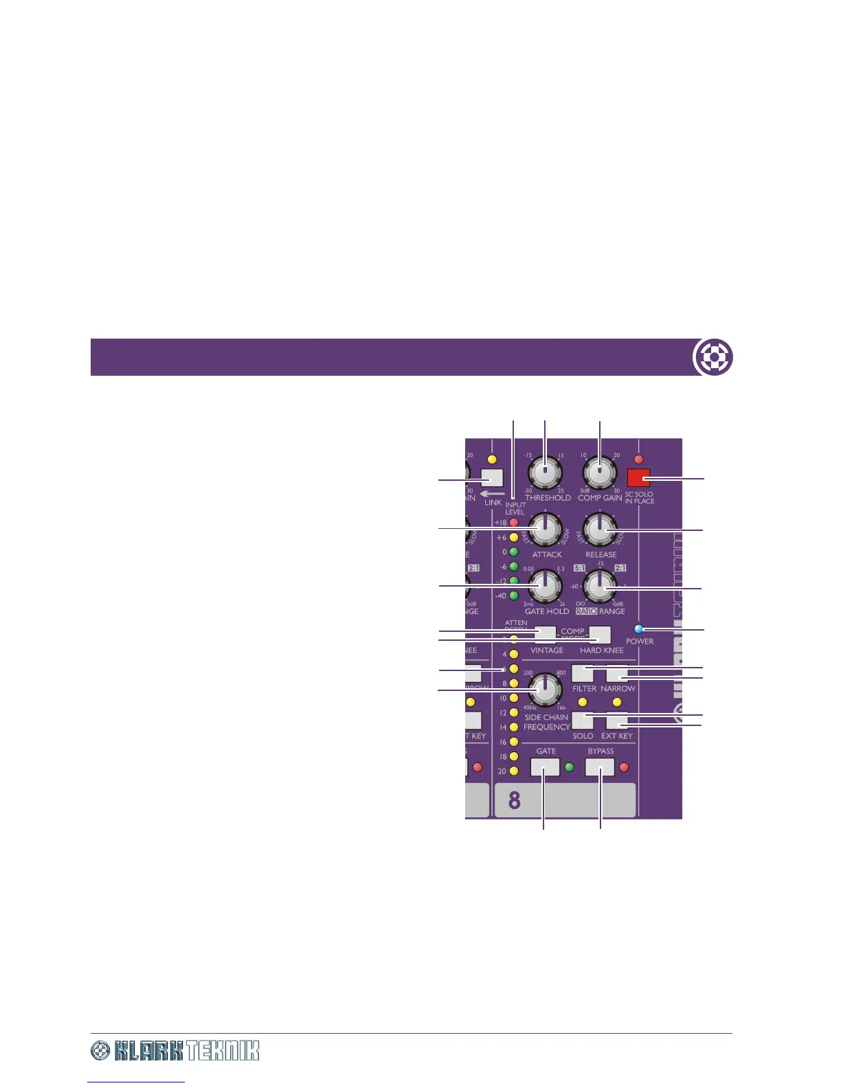
1 INPUT LEVEL meter (dBu): Dedicated peak
reading, six-segment audio level LED meter that
monitors the input XLR level at all times, no matter how
the controls are set.
2 THRESHOLD control knob: Adjusts the
operating point for the compressor or gate, depending on
which is selected.
3 COMP GAIN control knob: Adjusts compressor
gain - also known as the make up gain - so that the level
of the outgoing compressed signal can be matched to the
incoming uncompressed signal.
4 SC SOLO IN PLACE switch with red LED:
Master solo in place (SIP) switch with red enabled/
disabled LED indicator. When enabled, all the SOLO
switches change function so that no signal will be
sent to the master solo output bus, and the side
chain signal will be sent directly to the output XLR
on the same channel when the SOLO button is
pressed, thus replacing the dynamics output signal.
5 RELEASE control knob: Adjusts the time it takes
the compressor to recover or the gate to close after the
programme material falls back below threshold,
depending on which is selected.
6 RATIO/RANGE control knob: Adjusts the
amount of compression (ratio) or gain reduction (range)
applied to signals below threshold, depending on which is
selected.
7 Blue POWER LED: Illuminates to indicate that
mains power is being applied to the unit.
8 FILTER switch: Used in conjunction with the NARROW switch and SIDE CHAIN FREQUENCY control knob to
provide a variable frequency band pass filter that acts on the side chain signals. This switch enables (switch = in) or
bypasses (switch = out) the filter.
9 NARROW switch: Changes the bandwidth from wide (switch = out) to narrow (switch = in), see Item 8 above.
10 SOLO switch with yellow LED: Enabling the SOLO switch with SIP disabled, sends post-filter side chain audio to
the solo bus output. If EXT KEY switch is enabled, the solo signal will be sourced from the EXT KEY input jack instead of
the input signal. Please be aware that if you enable the SOLO switch with SIP enabled, the side chain signal is
routed directly to the output.
20
2
3
4
5
6
7
8
19
15
14
1
17
18
9
10
11
12
13
16