Section 2
Installation
20412922
8-2012/Rev 10
2-6
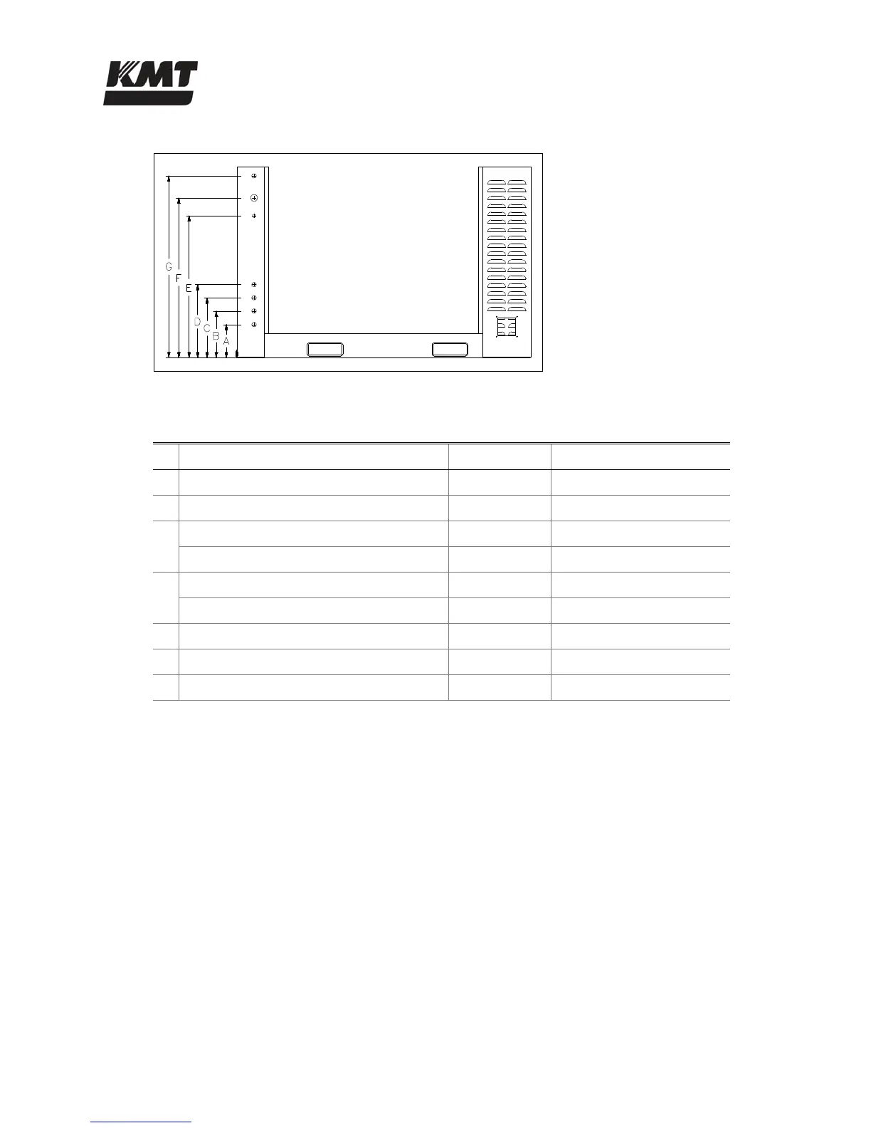
Figure 2-3: Service Connections
Table 2-4
Service Connections
Connection Height
A Drain 1/2” NPT 7.50” (191 mm)
B Cutting Water In 1/2” NPT 10.50” (267 mm)
C Cooling Water In (oil-to-water models) 1/2” NPT 13.50” (343 mm)
Hydraulic Oil In (air-to-water models) 3/4” JIC
D Cooling Water Out (oil-to-water models) 1/2” NPT 16.50” (419 mm)
Hydraulic Oil Out (air-to-water models) 3/4” JIC
E Plant Air In 1/4” NPT 32.00” (813 mm)
F Cutting Water Out 9/16” HP 36.00” (914 mm)
G Contaminated Waste Drain 1/2” NPT 41.00” (1,041 mm)
Cooling Water (Oil-to-Water Models)
Inlet cooling water flows through the oil-to-water heat exchanger in the hydraulic system to
control heat build-up in the hydraulic oil. The cooling water is then discharged through the
cooling water out port to either the drain or routed to a customer supplied water chiller.
Cooling water supply piping must be sized to meet the flow and pressure requirements of the
specific equipment. If municipal or well water is used for cooling, ensure the supply flow and
pressure meet the requirements in Table 2-7, Service Connection Specifications.
If a facility-wide chilled water system is used for cooling, ensure there is a minimum of 35 psi
(2.4 bar) pressure differential between the facility supply and discharge plumbing. Installation of
an in-line pressure boosting pump may be necessary to provide adequate cooling flow. Dedicated
chilled water systems should be sized according to pump horsepower as illustrated in Table 2-5,
Chilled Water Systems.
 Loading...