Section 9
High Pressure Water System
20412997
8-2012/Rev 12
9-26
8. Thoroughly clean the bushing retainer flange, including the cross-drilled weep holes.
Install the retainer flange over the plunger.
9. Install the retaining ring, ensuring the retaining ring fully seats inside the groove in the
hydraulic cylinder head.
The o-rings on the hydraulic cartridge will take up clearance. Tap lightly on the bushing
retainer flange with the plunger removal tool to compress the o-rings enough to start the
retaining ring in the groove. Use a flat blade screwdriver to push on the outer edge of the
retainer flange while working one end of the retaining ring into the groove. The retainer
flange should tilt or tip enough to allow the retaining ring to move into the groove.
Continue working the ring into the groove while tilting the retainer flange until the ring is
fully seated.
10. Install the high pressure cylinder assembly into the hydraulic cylinder head, following the
procedure, High Pressure Cylinder Assembly Installation.
11. Connect the high and low pressure water piping and turn the low pressure water supply
on.
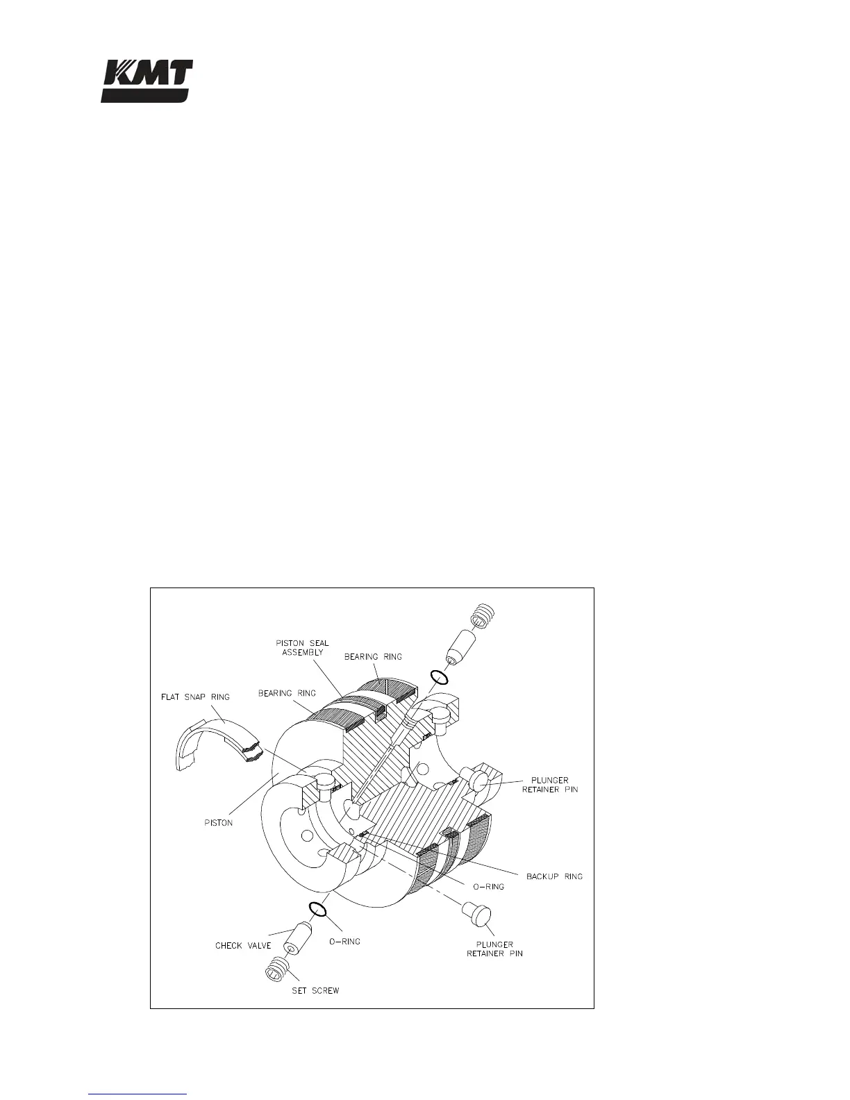
9.12 Hydraulic Piston
Two bearing rings provide wear contact between the piston and the inside diameter of the
hydraulic cylinder. On each end of the piston, six retainer pins hold the plunger in position. The
plunger retainer pins are held in place by a flat snap ring. Two internal check valves vent
unwanted hydraulic pressure from one side of the piston to the other, preventing pressure from
building behind the plunger button.
Figure 9-19: Hydraulic Piston Components
 Loading...