Installation, mounting and connection LABOPORT Pumps and Systems
28 Translation of original Operating Instructions, english, KNF 121211-121345 01/10
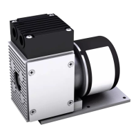
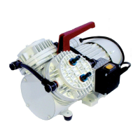
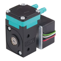
7.6. Gas Ballast
Only for two-headed pumps.
Motor disconnected from mains and de-energized
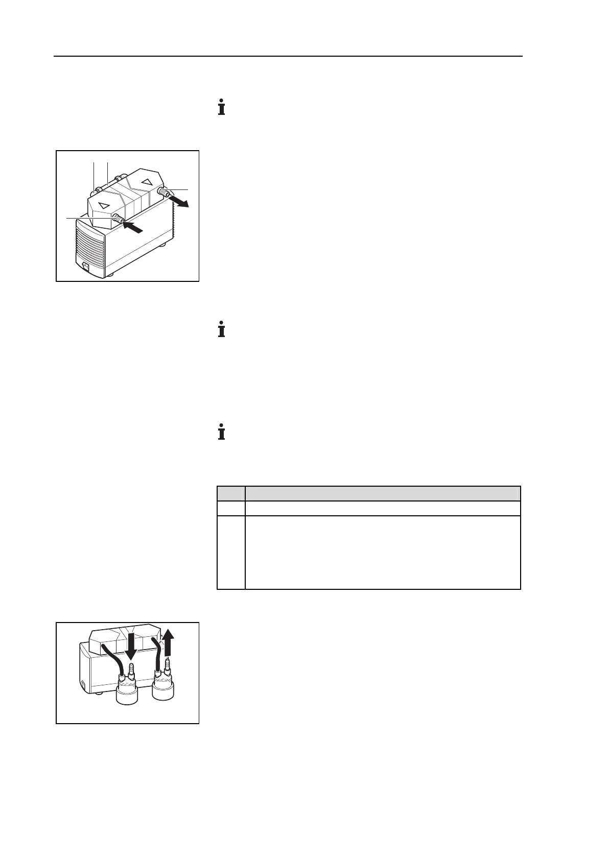
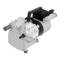
Mounting
1. Disconnect the tubes from the inlet (4) and the outlet (3) of the
pump.
2. Remove the pump from the baseplate.
3. Open the connection (2) of the pump heads.
4. Screw out the connecting piece (1) of the vacuum side head.
5. Screw the gas ballast into the pump head.
6. Remount the connection (2) between the both pump heads.
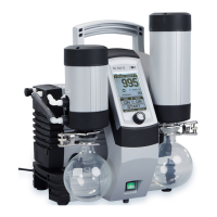
7.7. Mounting of Systems
The displayed system tube configuration is for two-headed
pumps only.
Contact KNF Service for information about laying tubes for
one-headed pumps and pumps with aluminum heads (“A” in
the type designation).
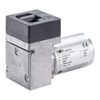
7.7.1. System SR
The system SR consists of:
baseplate
two separators
Qty Material
1 Phillips-head screwdriver No. 3
2 Tubes (see fig. 14)
Resistant to the medium employed
Inside diameter 10 mm
Length: approx. 150 mm
Tab. 17
1. Attach pump to the baseplate (see chapter 7.2, page 24).
2. Install the separators (chapter 7.3, page 24).
3. Lay tubes for separators (see fig. 14).
Condition
12
3
4
Fig. 13: Mounting the gas ballast
Tools and material
Fig. 14: Tubing system SR