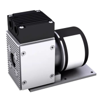
Installation, mounting and connection LABOPORT Pumps and Systems
30 Translation of original Operating Instructions, english, KNF 121211-121345 01/10
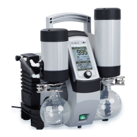
7.7.3. System SC
The system SC consists of:
Baseplate
1 separator
1 high performance condenser
Electrical supply unit with 1 vacuum controller
Qty Material
1 Phillips-head screwdriver No. 3
1 Allen key 4 mm
1 Allen key 5 mm
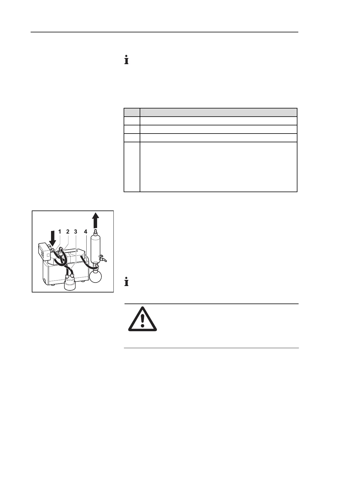
4 Tubes (see fig. 17)
Resistant to the medium employed
Inside diameter 10 mm
Length: (1,4) approx. 220 mm, (2) approx. 300 mm,
(3) approx. 150 mm
Tab. 19
1. Attach pump to the baseplate (see chapter 7.2, page 20).
2. Install the separator (see chapter 7.3, page 20).
3. Install the high performance condenser (see chapter 7.4, page
21).
4. Install the electrical supply unit and the vacuum controller (see
chapter 7.5, page 21).
5. Lay hoses for system (see fig. 17).
Coolant inlet and outlet see fig. 16.
When using a coolant valve:
WARNING
Danger of the high performance condenser bursting
Make sure that the coolant valve is mounted
between the coolant supply and the coolant inlet
port of high performance condenser.
6. Wire and connect with each other the electrical supply unit and
the vacuum controller (see chapter 7.5, page 21).
Tools and material
Fig. 17: Tubing system SC