Table of Contents Page
1. Description 2
1.1 Unit Functions 2
1.2 Arrangement in
Vacuum Systems 2
1.3 Mechanical Attachment 2
1.4 Electrical Connection 2
1.5 Pneumatic Connection 2
1.6 Switching on/off 2
1.7 Explanation of Display
Elements 3
1.8 Explanation of Control
Panel 3
2. General Safety
Precautions 3
3. General Operating
Instructions 3
3.1 Operating Conditions 3
3.2 Starting 3
3.3 Shutdown 4
4. Manual Operation 4
4.1 Controlling Profiles 4
4.2 Setting Values 5
4.3 Running 5
4.3.1 Controlling 5
4.3.2 Controlling with soft
setpoint start 5
4.3.3 Controlled Pressure
Reduction 5
4.4 Temporary Mode 6
4.4.1 Function and Operation 6
4.4.2 Aeration during Distillation 6
4.4.3 Experimental Use 6
4.5 Uncontrolled Evacuation/
Drying Mode 6
5. Automatic Operation 7
5.1 Controlling Profiles 7
5.2 Setting Values 7
5.3 Running 7
6. Changing of Pressure unit 8
7. Calibration 8
8. Trouble Shooting 8
9. Specifications 8
10. Ordering Information 8
10.1 Accessories 8
10.2 Vacuum Controller and
Vacuum Valves 8
1. Description
NC 800: For use at LABOPORT vacuum
systems.
NBC 800: Workstation vacuum control-
ler for use e. g. at vacuum supply
points.
Technical data: see chapter 8.
1.1 Unit Functions
The vacuum controller NBC 800 regula-
tes vacuum on an individual basis in
the laboratory working place. Several
different functions are possible:
Evacuation at pressure setpoint;
regulation by pressure setpoint and
pressure differential (manual ope-
ration);
defined post distillation;
experimental use;
automatic search for distillation
point (automatic operation).
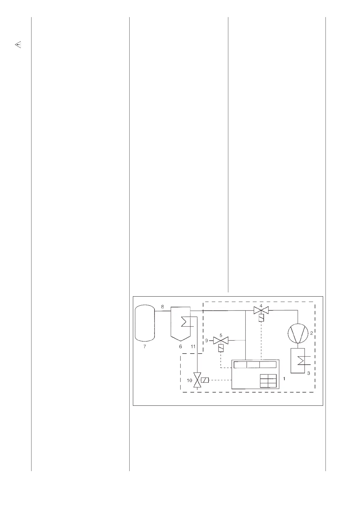
1.2 Arrangement in Vacuum Systems
See fig. 1.
1.3 Mechanical Attachment
The Vacuum Controller NBC 800 can be
attached to a round support by means
of the connection on its back side
(maximum support diameter: 13 mm).
Other types of connection on request.
Attachment in LABOPORT
®
Sys-
tems: see LABOPORT Operating
Manual.
1.4 Electrical Connection
Electrical supply:
The socket is located on the back
of the unit.
Cooling water valve and vacuum
valve:
Both can be connected either to
the side socket or the socket on
the back (6-pin). Proper connec-
tions are ensured by means of
different pin arrangements.
Insert plug into a properly installed
safety socket.
Electrical Connection in
LABOPORT
®
Systems: see
LABOPORT Operating Manual.
1.5 Pneumatic Connection
The pneumatic connection is made
at the valve block on the hose shaft
(tube ID 10mm).
Pneumatic Connection in
LABOPORT
®
Systems: see
LABOPORT Operating Manual.
1.6 Switching on/off
The vacuum controller is switched
on and off by the switch on the
side.
Symbols: = Position in the illustration, = Important point, = Task, = Advice to users, = Product information Warning
2 Translation of original Operating Instructions, english, KNF 121205-121650 02/10
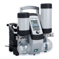
Fig. 1: Arrangement of vacuum controller in vacuum system
Specification:
1 Vacuum controller NBC 800
2 Vacuum pump
3 High Performance Condenser of
Vacuum System
4Vacuum valve
5 Venting valve (internal)
6 Condensate recipient
7 Vacuum installation
8 Suction line
9Cleaning gas connection/Aeration
10 Coolant valve (accessory)
11 Cooling water tubing