I.7.2 Permissible ambient conditions, ventilation, mounting position
Storage temperature/humidity,
storage duration
ð VI.1
Transport temperature / humidity
ð VI.1
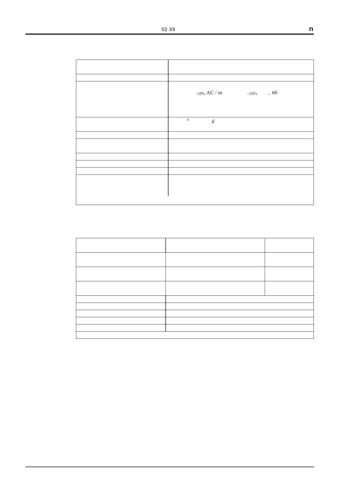
Supply voltage tolerances
Input power
Aux. power supply
without brake
with brake
min 3x230V
-10%
AC / max 3x 480V
+10%
, 50 ... 60 Hz
20...36 V DC
24 V DC (-0% +15%)
Ambient temperature in operation
0to+40
o
C at rated data
+40 to +55°C with power derating 2.5% / °C
Humidity in operation rel. humidity 85%, no condensation
Site altitude
up to 1000m a.m.s.l. without restriction
1000 — 2500m a.m.s.l. with power derating 1.5%/100m
Pollution level Pollution level 2 to EN60204/EN50178
Enclosure protection IP 20
Mounting position
generally vertical. ðII.2
Ventilation
SERVOSTAR™ 601/603
SERVOSTAR™ 606-620
natural convection
built-in fan
Make sure that there is sufficient forced ventilation within the switchgear cabinet.
I.7.3 Conductor cross-sections
Following EN 60204, we recommend for single-axis systems :
AC connection
SERVOSTAR™ 601-610 : 1,5 mm²
SERVOSTAR™ 614/620 : 4 mm²
DC-link
SERVOSTAR™ 601-610 : 1,5 mm²
SERVOSTAR™ 614/620 : 4 mm²
Shielded,
for lengths > 20 cm
Motor cables up to 25 m length
SERVOSTAR™ 601-610 : 1 - 1,5 mm²
SERVOSTAR™ 614/620 : 2,5 mm²
shielded
Motor cables 25 to 100 m length
(consult our applications department)
SERVOSTAR™ 601-606 : 1 mm²
SERVOSTAR™ 610-620 : 2,5 mm²
Shielded,
with motor choke
Resolver, thermostat-motor 0.25 mm² twisted pairs, shielded, max.100m
Setpoints, monitors, AGND 0.25 mm² twisted pairs, shielded
Control signals, BTB, DGND 0,5 mm²
Holding brake (motor) min. 0.75 mm², shielded, check voltage drop
+24 V / XGND max. 2.5 mm², check voltage drop
For multi-axis systems, please note the special operating conditions in your installation
Technical data for connection cables. ð II.3.5 .
I.7.4 LED display
A 3-character LED display shows the amplifier status after switching on the 24V supply
(ð IV.2.2). During operation and parameter setting of the amplifier via the keys on the front panel,
the parameter and function numbers (ð IV.2.2.2) are displayed, as well as the numbers of any
errors which occur (ð IV.3).
16 SERVOSTAR™ 600 Installation-manual
General
02.99
Kollmorgen
 Loading...