EasyManuals Logo

Kollmorgen Seidel SERVOSTAR 600 Series Assembly, Installation And Commissioning Instructions

Kollmorgen Seidel SERVOSTAR 600 Series
68 pages
To Next Page IconTo Next Page
To Previous Page IconTo Previous Page
Page #38 background imageLoading...
Page #38 background image
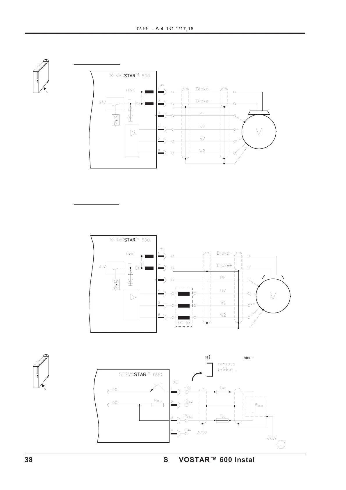
III.2 Motor connection with brake (X9)
Lead length £ 25m
Lead length >25m
For lead lengths above 25m the choke box 3YL-xx must be wired into the motor lead, close to the
amplifier (please consult our applications department).
III.3 External regen resistor (X8)
Remove the plug-in link between the terminals X8/1 (-R
B
) and X8/2 (+R
bint
).
- A.4.031.1/17,18
38 SERVOSTAR™ 600 Installation-manual
Interfaces
02.99 - A.4.031.1/17,18
Kollmorgen

Table of Contents

Other manuals for Kollmorgen Seidel SERVOSTAR 600 Series

Questions and Answers:

Question and Answer IconNeed help?

Do you have a question about the Kollmorgen Seidel SERVOSTAR 600 Series and is the answer not in the manual?

Kollmorgen Seidel SERVOSTAR 600 Series Specifications

General IconGeneral
BrandKollmorgen Seidel
ModelSERVOSTAR 600 Series
CategoryAmplifier
LanguageEnglish

Related product manuals