The following notes should assist you to carry out the installation in a sensible sequence, without
overlooking anything important.
In a closed switchgear cabinet. Observe Chapter I.7.2 .
The site must be free from conductive or corrosive materials.
For the mounting position in the cabinet ð II.2
Check that the ventilation of the servo amplifier is unimpeded
and keep within the permitted ambient temperature ð I.7.2 .
Keep the required space clear above and below the
servo amplifier ð II.2.
Assemble the servo amplifier and power supply close together
on the conductive, earthed mounting plate in the cabinet.
Select cables according to EN 60204 ð I.7.3
EMC-conform shielding and grounding (ð II.3.1)
Earth the mounting plate, motor housing and CNC-GND
of the controls..
Notes on connection techniques are in Chapter II.3.4.2
— Route power leads and control cables separately
— Wire the BTB/RTO contact in series into the safety
loop of the installation
— Connect the digital control inputs to the servo amplifier
— Connect up AGND
— Connect the analog setpoint, if required
— Connect up the feedback unit (resolver or encoder)
— Connect the encoder emulation, if required
— Connect the expansion card (see corresponding
manual on the CD-ROM)
— Connect the motor leads
Connect shielding to EMC connectors at both ends
Use motor chokes (3YLxx) for lead lengths >25m
— Connect motor-holding brake, connect shielding to EMC
connectors at both ends
— If required, connect the external regen resistor
(with fusing)
— Connect aux. supply
(for max. permissible voltage values ð I.7.2)
— Connect main power supply
(for max. permissible voltage values ð I.7.2)
— Connect PC (ð III.7).
— Final check of the implementation of the wiring,
according to the wiring diagams which have been used.
SERVOSTAR™ 600 Installation-manual 25
Kollmorgen
02.99
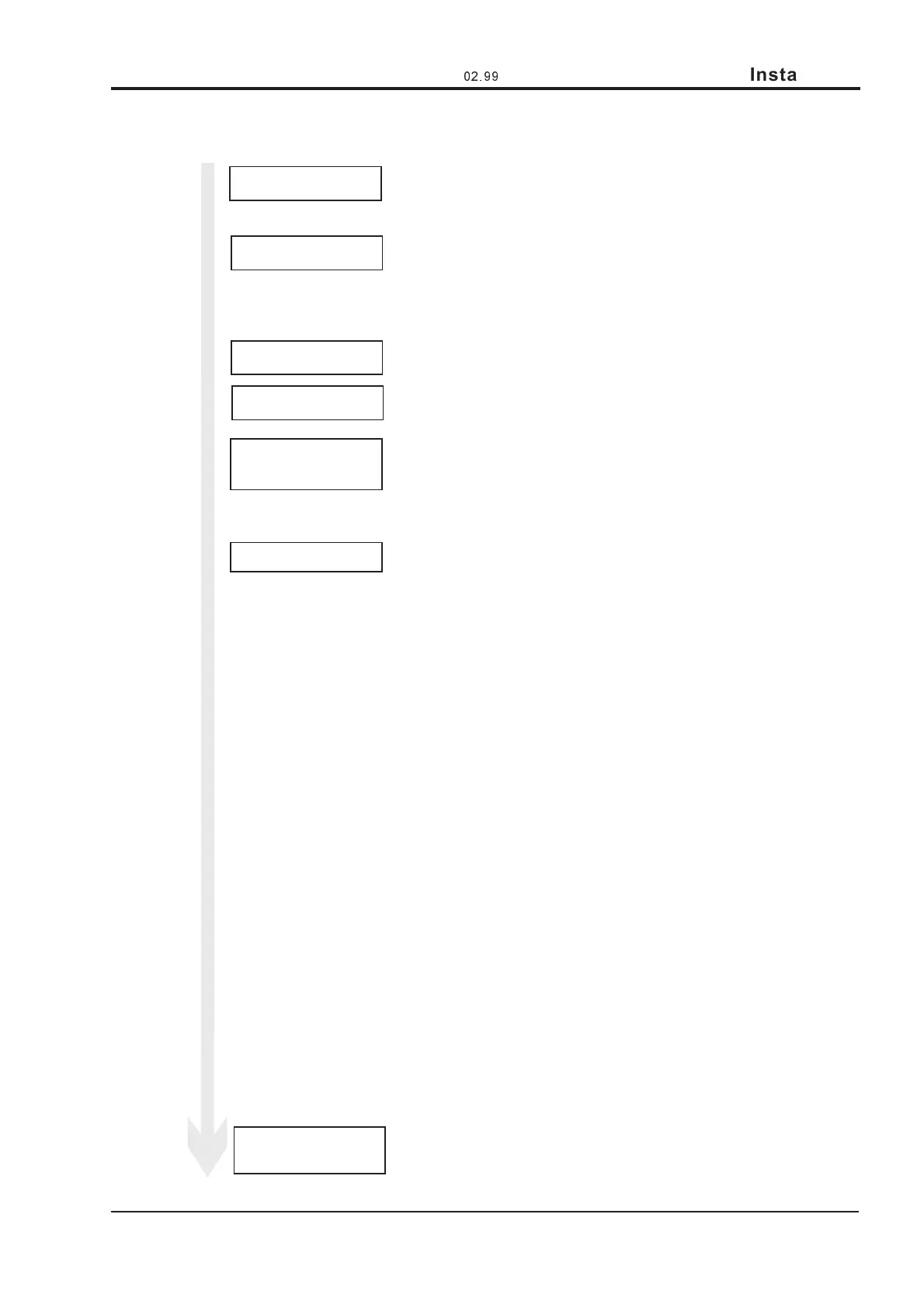
Installation
Site
Ventilation
Assembly
Grounding
Shielding
Cable selection
Final check
Wiring
 Loading...