26.03.1996 • KHH SEENXL13A
•For Authorized KCI Service Agents Only•
KCI Hoists Corporation reserves the right to alter or amend the above information without notice
Page 22
XL
Service Manual
CU1
KCI KONECRANES GROUP
KCI HOISTS CORPORATION
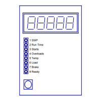
6.5 The red Brake-light is lit or blinking
1 See Chapter 3.8 to check the normal operation of the brake wearing control
circuit.
2 Measure the resistance of the brake wear sensor to check the condition of the
brake.
a) Normal resistance is about 0 ohm and it is insulated from PE (ground).
- If the resistance is very big or the brake wear sensor contacts to the PE
(ground), check the wiring and renew the friction disks of the brake if
necessary.
3 If the resistance is OK, bypass the brake wear sensor by connecting a jumper
between CU1:15 and CU1:16 and try to lift. See note 1.
a) If the lifting works now correctly, check the brake again (step 2).
b) If the lifting doesn't work, check to see that there is voltage in CU1:11 and
CU1:12 (ca. 18 VAC).
-If the voltage is ca. 18 VAC, change the CU1.
c) Remove the jumper between CU1:15 and CU1:16.
6.6 The CU1's front panel is out and hoisting is prevented
1 Same action as with 'Err_3' trouble shooting. See Appendix 2.
6.7 The CU1 is hot and it doesn't work correctly
1 Check voltages between CU1:5 and CU1:6 (ca. 11 VAC) as well as between
CU1:11 and CU1:12 (ca. 18 VAC). Note to check these voltages are at the CU1's
connector.
a) If the voltages are reversed, check and correct the wiring.
b) If the voltages are OK, change the CU1.
6.8 The load sensor signal fluctuates
1 Check the fitting of the load sensor.
2 Measure the supply voltage to the load sensor between CU1:2 and CU1:4. It
should be steady and about 9,85 VDC. Measure also the load sensor output
signal voltage between CU1:2 and CU1:3 (3,9...6,6 VDC).
a) If the voltages are not OK, check the load sensor circuit. Note that the
maximum current for the CU1's load sensor circuit is 100 mA.
b) If the voltages are OK, change the CU1.