Shenzhen Anycubic Technology Co., Ltd.
12
Fig. 27
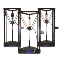
Step 3. As shown in Fig. 28, mount 4 pieces of square nuts (C11) into the corresponding
position on bottom Al extrusion, and fix ANYCUBIC mainboard using 4 pieces of C15. Note:
in Fig. 28, 3 motors are named as X, Y, Z respectively in order to make the
wiring/interpretation clearer in the following paragraph. The assembly position of
ANYCUBIC mainboard could be referred to those 3 motors.
Fig. 28
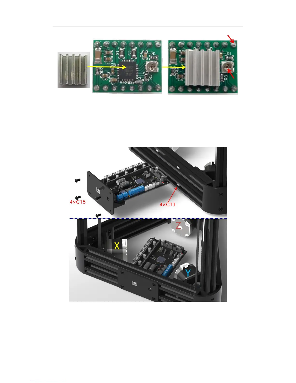
Step 4. Next, as shown in Fig. 29, fix 4 pieces of A4988 onto ANYCUBIC mainboard. Pay
closely attention to the configuration and direction of the drivers and board to avoid any
unnecessary problem/damage during use.