5 Function description
5.1 Structure
5 Function description
5.1 Structure
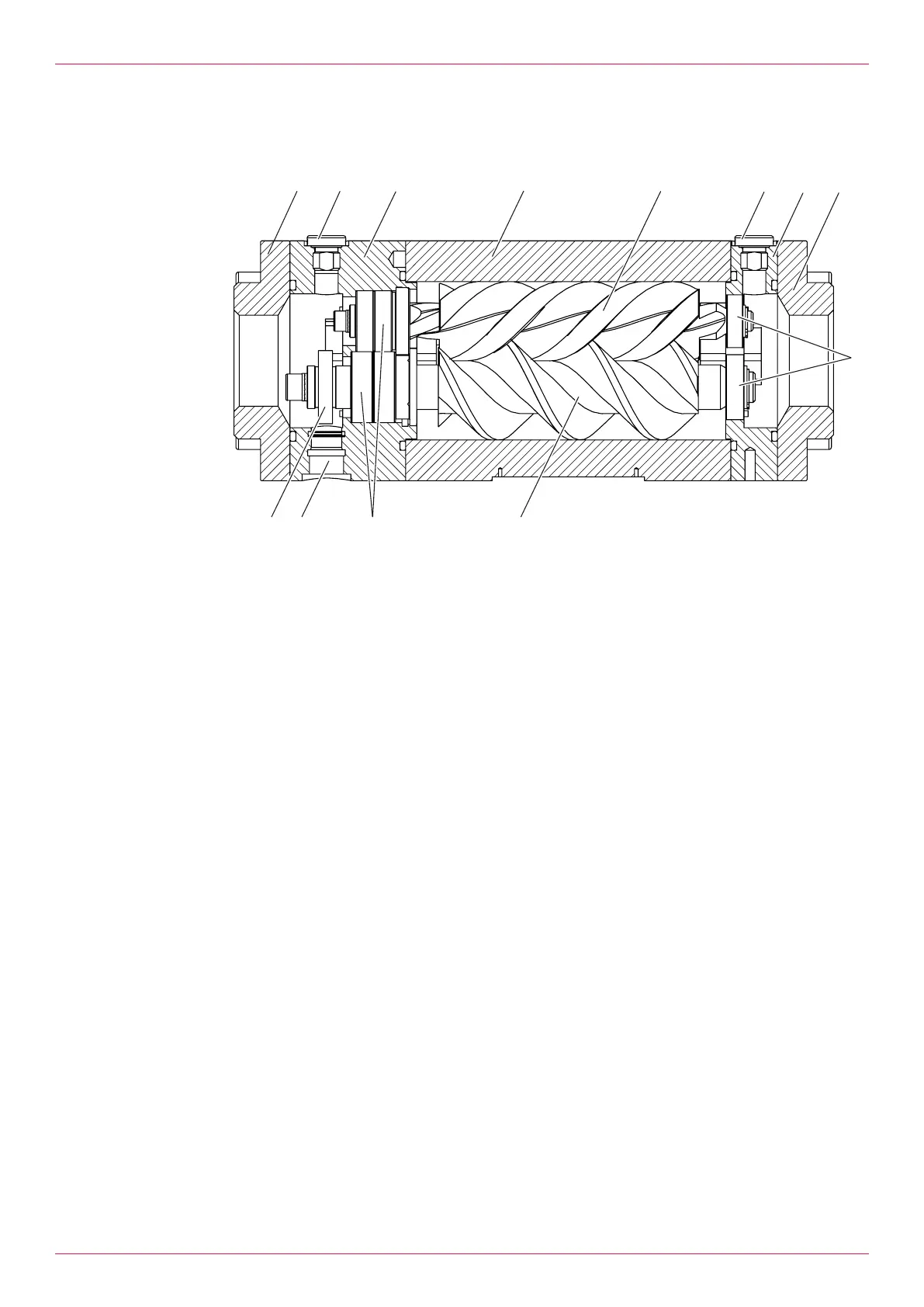
Fig.6: Structure of the flowmeter
1 Connection 6 Ball bearing floating bearing end
2 Screw plug 7 Measuring screw large
2a Connection of temperature sensor 8 Ball bearing fixed bearing end
3 Bearing cover 9 Pick up hole
4 Measuring housing 10 Pole wheel
5 Measuring screw small
5.2 Functional principle
Flowmeters belong to the group of rotating displacement meters as screw meters. The pumped liquid
makes the measuring unit rotate. The displacement effect results from the continuous filling, axial dis-
placement and discharge of the volumes that are formed by the measuring housing and measuring
unit. The measured pumped liquid flows around and lubricates all the rotating parts. Thanks to the dis-
placement principle, the flowmeter does not require inlet sections and smoothing sections at the feed
line and outlet.
Depending on the customer requirements, the flowmeters can be equipped with suitable end connec-
tions for connection to various flanges.
5.3 Rolling bearings
Thanks to precision rolling bearings the measuring unit operates contact-free and with low friction in
the housing of the flowmeter. The bearing on the side of the pole wheel is realized as a fixed bearing.
The following bearings are used depending on the size:
o Single-row deep-groove ball bearings
o Angular-contact ball bearings arranged in pairs
o Four-point contact bearings
The bearing position on the opposite side of the measuring unit is realized for all sizes with a displace-
able deep-groove ball bearing as a floating bearing.
Operating instructions
OIO 14en-GB Edition 2020-01
19
 Loading...