16 Accessories
16.2 Junction box
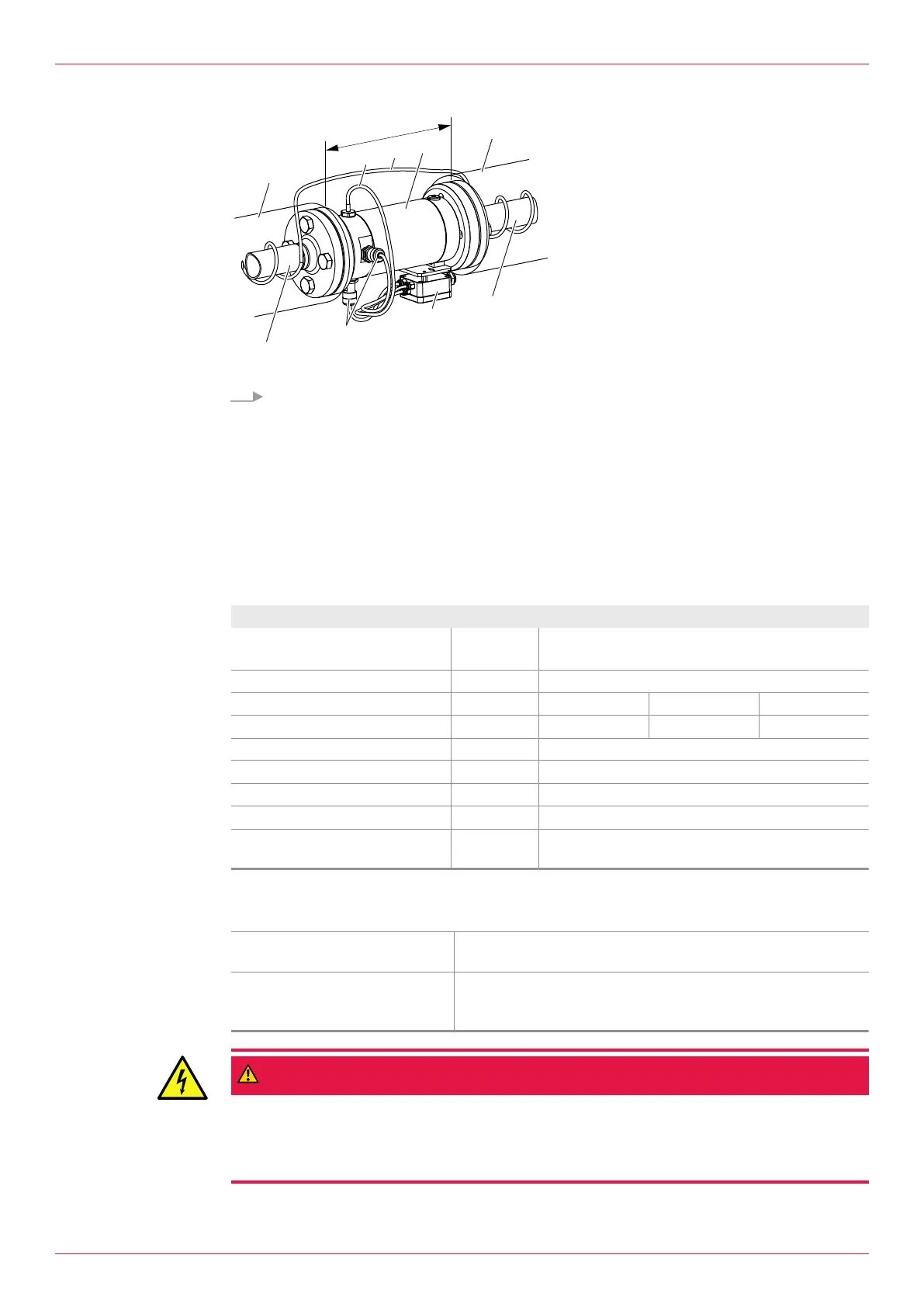
Fig.10: Flowmeter with trace heating
1 Thermal insulation
2 Temperature sensor
3 Heating line
4 Flowmeter
5 Piping
6 Junction box
7 Pick up with connecting cable
X Area necessarily without thermal
insulation
Wind the heating line3 around the piping5. Ensure that the pick up7, temperature sensor2,
junction box6 and associated cables are not thermally insulated. The areaX must remain free of
thermal insulation.
16.2 Junction box
16.2.1 Function description
For the flowmeters the manufacturer offers a junction box. This simplifies the electrical connection of
the various sensors.
16.2.2 Technical data
Unit UZA 09 UZA 10 UZA 11
Suitable for Pick up BEG43, BEG44
Temperature sensor EET32, EET33, EET34
Electrical specification
o Number of sensor inputs
1 2 3
o Number of outputs
1 1 1
Mechanical specification
o Max. liquid temperature
[°C] 150
o Housing material
Aluminium
o Connection thread
M6
o Fastening
Direct installation on the flowmeter (except
OMG-013)
Tab.18: Junction box
16.2.3 Installing the junction box
Personnel qualification: o Fitter
o Electrician
Personal protective equipment: o Work clothing
o Protective gloves
o Safety boots
DANGER
Risk of death resulting from electric shock.
► Ensure that the electrical power supply is de-energized and is secured against being switched
back on.
► Observe the operating instructions of the electrical components.
Operating instructions
OIO 14en-GB Edition 2020-01
51
 Loading...