16 Accessories
16.3 Extension cable
1
2
4
5
3
BEG 1 BEG 2 EET
BEM
1
0 V Q
1
24 V Q
2 98
Com. t
34 675
2 63 4 5 7
Sig.2 Q
Sig. t
Com. t
24 V Q
Sig.1 Q
0 V Q
Sig. t
24 V Q
Com. t
Com. t
Sig.1 Q
Sig.2 Q
0 V Q
8
6
7
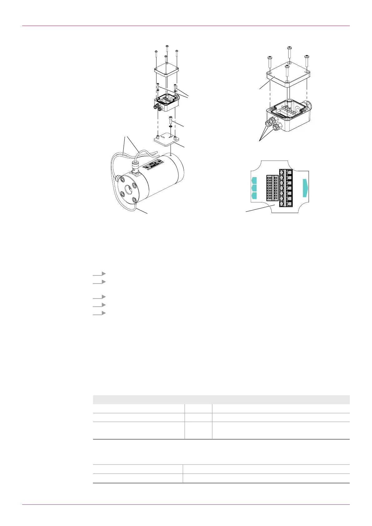
Fig.11: Installing and connecting the junction box
1 Temperature sensor cable 5 Socket screw and washer
2 Pick up cable 6 Cable gland sensor inputs
3 Junction box base plate 7 Junction box cover
4 Socket screw and washer 8 Connection diagram
1. Pinch off the pick up cable2 and temperature sensor cable1. Ensure sufficient cable length.
2. Fasten the base plate3 of the junction box to the flowmeter using the socket screw and
washer4.
3. Fasten the lower part of the junction box to the base plate using socket screws5.
4. Carry out the cabling through the cable gland6. Observe the connection diagram8.
5. Screw tight the cover7 of the junction box.
16.3 Extension cable
16.3.1 Function description
Normally the cable length does not influence the functionality of the sensors. Nevertheless the manu-
facturer recommends that connecting cables of the junction box be extended to a maximum length of
100m. Extension cables as well cable connectors and cable box are available as accessories from the
manufacturer.
16.3.2 Technical data
Unit
Max. length [m] 100
Cable diameter [mm] 6.0 – 10.5
Wire cross-section min. – max. [mm
2
]
[mm
2
]
0.25 – 2.50 (single wire)
0.25 – 1.50 (multiple wires)
Tab.19: Extension cable
16.3.3 Connecting the extension cable
Personnel qualification: o Electrician
Personal protective equipment: o Work clothing
52
OIO 14en-GB Edition 2020-01
Operating instructions
 Loading...