• Change a port name by clicking the name area and entering the new one.
• In the processing view, the module appears at the center and input/output volume sliders
appear to the left/right (for further information, see Input / Output Channels Operation
on page 19).
• To adjust the configuration, click and hold the configuration knob and then move the
mouse up or down, or enter the parameter value below the knob and press Enter on
your keyboard to apply.
• Reset a configuration knob to its default parameter value, by clicking the mouse within
the knob area while pressing Ctrl on your keyboard.
• The parameter value always appears below the knob or slider.
• A selected input or output button appears with a white rim.
• A selected processing tool button appears with a distinctive color.
• An enabled processing tool button appears with a distinctively colored rim.
Processing modules enable performing the following functions:
• Input / Output Channels Operation on page 19.
• Pre-Matrix Signal Processing on page 20.
• Post-Matrix Signal Processing on page 30.
Input / Output Channels Operation
This section describes the function of the input and output sliders (the examples in this
section, showing the inputs, apply also to outputs).
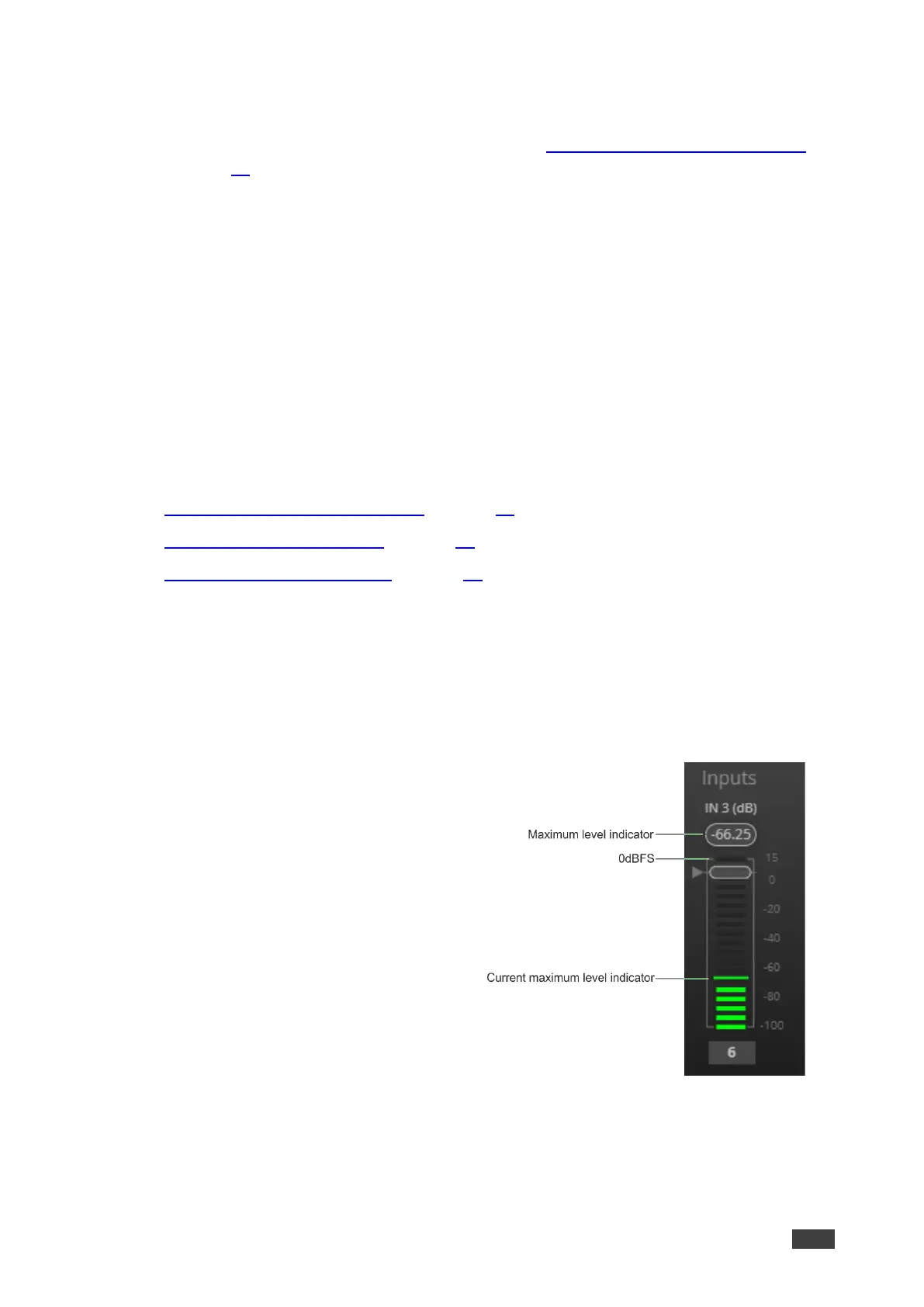
Level Measurement Indicators:
The audio signal enters the digital system at a
certain level and is measured in dBFS units
(dB relative to full scale, the maximum value).
• Maximum level indicator – shows the
highest registered level (in RMS) and
can change only if a higher level is
detected.
Click the indicator to reset to the current
maximum value.
• 0dBFS – refers to the maximum signal
level that can enter the system signal
levels higher than the system limit are
clipped.
• Current maximum level indicator –
displays the current maximum level and
holds it until a higher value is detected.