Connecting the VP-311DVI Automatic DVI / Audio Switcher
5
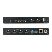
5 Connecting the VP-311DVI Automatic DVI / Audio Switcher
To connect
1
the VP-311DVI Automatic DVI / Audio Switcher (as illustrated
in Figure 2), do the following
2
:
1. Connect a DVI source (for example, an HDCP compliant DVD
3
) to the IN 1
DVI connector and connect the digital audio input
4
to the IN 1 S/PDIF RCA
connector.
2. Connect a DVI source (for example, a DVI computer graphics source) to the
IN 3 DVI connector and connect the digital audio input
5
to the IN 3 3.5 mini-
jack connector.
3. Connect the OUT DVI connector to the DVI acceptor (for example, a
DVI/HDMI plasma display).
4. Connect the AUDIO OUT S/PDIF RCA connector
6
and the AUDIO OUT 3.5
mini-jack connector to a digital audio acceptor (for example, an AV receiver).
5. Set the PRIORITY SETUP dipswitches (see section 5.1)
6. If required, connect a PC and/or controller to the RS-232 port (see section 5.3)
and/or the ETHERNET port (see section 5.4).
7. If required, connect
7
the contact closure remote control PINS (see section
5.2).
8. Connect the 12V DC power adapter to the power socket and connect the
adapter to the mains electricity.
1 You do not need to connect all the inputs
2 Switch OFF the power on each device before connecting it to your VP-311DVI. After connecting your VP-311DVI, switch
on its power and then switch on the power on each device
3 You can also connect a DVD player with an HDMI (High Definition Multimedia Interface) connector, using an HDMI-DVI
adapter to transfer video signals
4 Alternatively you can connect it to the 3.5 mini-jack connector
5 Alternatively you can connect it to the S/PDIF RCA connector
6 If the inputs are connected only to the 3.5 mini-jack connectors, connect the AUDIO OUT 3.5 mini-jack connector and/or
the BALANCED OUT terminal block connector only
7 The connection is not illustrated in Figure 2