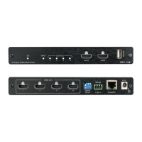
WP-5VH2 - Connecting the WP-5VH2
3. Connect a PC graphics source, (for example, a laptop) to the PC In input.
4. Connect an unbalanced stereo audio source, (for example, the audio output
from the laptop) to the AUDIO IN 3.5mm mini jack.
5. Connect the HDBT OUT RJ-45 connector on the rear panel of the
WP-5VH2 to an HDBT-compatible receiver (for example, the TP-588D or
TP-580Rxr).
6. Connect the AUDIO OUT 3-pin terminal block on the rear panel of the
WP-5VH2 to the unbalanced, stereo audio acceptor, (for example, a power
amplifier with speakers).
7. Connect the REMOTE, 5-way terminal block to momentary, contact-closure
switches, only on the WP-5VH2, (see Section 5.1).
8. If the device is not connected to a PoE provider, connect the power adapter
to the WP-5VH2 and to the mains power, (not shown in Figure 3).
Note: All LED supplies include a current limiting resistor and are designed to work
with any standard LED.
5.1 Connecting the Remote Control Switches
Note: Only applicable to the WP-5VH2.
You can connect remote, momentary-contact contact-closure switches to the
terminal block on the rear panel of the WP-5VH2 to control the device.
Figure 4 illustrates the connections from the terminal block to the contact-closure
switches.
Figure 4: Remote Switches Terminal Block