KWP
1
1 General
Your centrifugal pumps will only give you completely trouble
free and satisfactory service on condition that it is installed
with due care and properly maintained. It is absolutely essential
that the instructions contained in this manual be scrupulously
observed, and that the pumps are not operated under
conditions which differ from those specified under our
‘Operating Conditions’. This operating instruction manual does
not take any account of any safety regulations which may
apply to the installation site, and the Site Engineer or Site
Operator is responsible for notifying our erection staff of any
such regulations and seeing that they are complied with.
The type series pump size, main operating data and work
order number are all stamped on the name plate affixed to the
pump, please make sure to quote this information every time
you write to us in respect of queries, repeat orders and more
particularly when ordering spare parts.
1.1 Handling
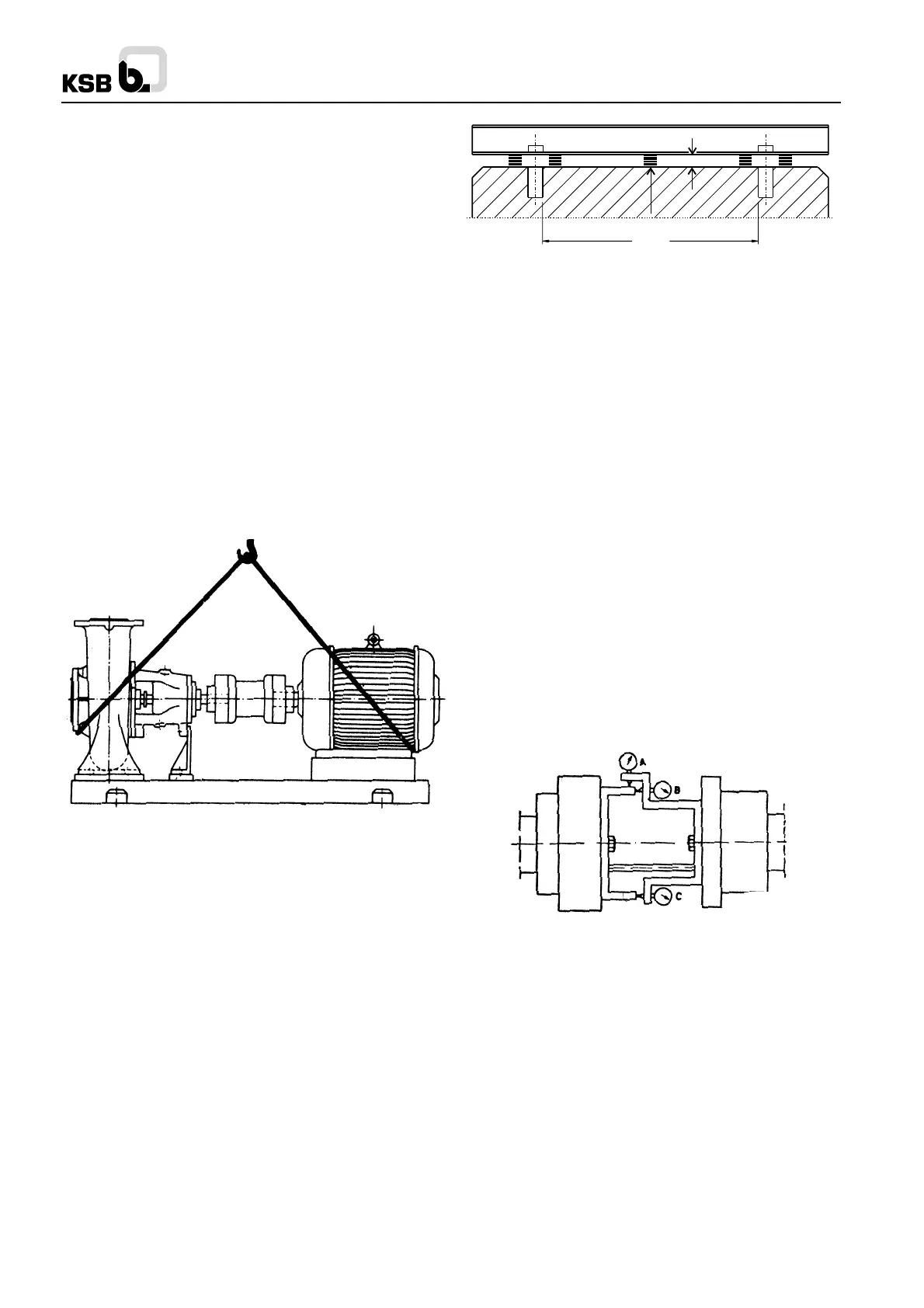
The pumping set should be properly handled and slug for
transport. Do not thread the ropes through the eye bolt on the
motor. See Fig. 1
During handling do not remove the rubber blankings provided
on the suction and discharge nozzles.
Fig. 1 Pump and driver mounted on combined base plate.
2 Installation (Installation on site.)
2.1 Foundation
Make sure that the concrete foundation has set firmly before
placing the base frame along with the pumping set or pump
on it. The surface of the foundation should be truly horizontal
and perfectly flat. The foundation bolts should be suspended
in the base plate.
2.2 Base frame and pump
Alter placing the base frame along with the pump on the
foundation, level it up with the aid of a master spirit level placed
on the discharge nozzle and motor pads.
The correct gap between the two coupling halves specified on
the foundation drawing must be observed.
Ground plates should always be inserted to the left and right
of the foundation bolts in close proximity to the bolts
themselves between the base plate or foundation frame and
the foundation itself. If the spacing between adjoining anchor
bolt holes exceeds 800 mm, additional plates should be
inserted half away between the adjoining holes. All plates must
lie perfectly flush.
Fig. 2 Provision of necessary ground plates
To ensure silent running, the pumping set can be mounted on
vibration dampers (please consult us first). Compensators can
be arranged between the pump nozzles and the suction and
discharge lines.
After insertion of the foundation bolts, the latter should be
grouted in the foundation with grouting mix. When the mix
has set firm, the base plate should be levelled up in accordance
with section 1.3 and the foundation bolts should be tightened
uniformly ad firmly. Thereafter the base plate should be grouted
in with mix (non shrinking mix if possible), making sure that
no cavities remain unfilled. Use vibrator, if necessary.
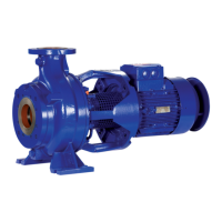
2.3 Alignment of pump and driver
Accurate coupling alignment requires the manufacture of a
coupling alignment jig. This can be made from 20 x 20 flat bar
steel. The jig should be attached to the shaft.
See Fig. 3.
The coupling can be considered correctly aligned with the aid
of the jigs illustrated if the difference measured does not exceed
0.04 mm both in the radial and axial directions, measurements
being taken in 4 planes at 90
0
C intervals. The coupling
alignment check should be repeated after the piping has been
connected to the pump to ensure stress free piping. Prior to
alignment individual concentricity of coupling should be
checked. It should be within 0.03 mm, if not corrective action
should be taken. The coupling should be dynamically balanced
in accordance with VDI 2060 (ISO 1940) Q 6.3 for motor driven
and Q2.5 for turbine driven pumps.
Fig 3. Alignment of a spacer type coupling
2.4 Connecting the piping
Never use the pump itself an anchorage for the piping. Suction
lift lines should be laid with a rising slope towards the pump
and suction head lines with a downward slope towards the
pump. The pipe lines should be anchored in close proximity
to the pump and should be connected to the latter without
transmitting any stresses or strains nor should the weight of
the piping be loaded on to the pump.
The nominal sizes of the pipelines should be at least equal to
the nominal sizes of the pump nozzles. We recommend the
incorporation of check valves or non return valves and isolating
valves in the system, depending on the type of installation
and pump. Any thermal expansion of the piping (due to high
temperatures) must be compensated by suitable means, so
as not to impose any additional load on the pump.
>800
min. 50 mm