KWP
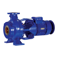
2.4.1 Auxiliary connections.
The auxiliary connections required for your pump (sealing
liquid, as the case may be ) are indicated on the installation
drawing. For sizes and details of connections see Table-1
Fig. 4 : Auxillary connections
Table 1
2.4.2 Vacuum balance line
If the pump has to pump a liquid out of a vessel under vacuum,
it is advisable to install a vacuum balance line. This line
should have a nominal size of 25mm at least. It should be
arranged to lead back in to the vacuum vessel at a pint above
the highest permissible liquid level. An additional line starting
at the pump discharge nozzle facilitates venting of the pump
before start up. The vacuum-tight isolating valve E in this
connecting line should be closed after the venting procedure
and should remain closed while the pump is running. The main
isolating valve C in the vacuum balance line must remain open
at all times when the pump is running and should only be
closed when the pump is shut down (Fig. 5)
Fig.5 : Vacuum balance line
2.4.3 Coupling guard
In compliance with the accident prevention regulations, the
pump may only be operated if it is fitted with a coupling guard.
If the customer states specifically that this coupling guard is
not to be supplied by us, it must be provided by the pump
operator.
2.5 Measuring instruments
Each pump should be equipped with two pressure gauges,
one at the suction nozzle and other at the discharge nozzle;
their measuring range should be suitable for the prevalent
pressure conditions, and they should be provided with a stop
valve. If the suction conditions demand it (e.g suction lift
operation), the gauge on the suction nozzle should be pressure
vacuum gauge.
2.6 Final check
Check the alignment once more as described in section 1.3. It
must be possible to rotate the pump rotor without effort by
hand at the coupling.
3 Commissioning, start-up /
shutdown
3.1 Preliminary remarks regarding
commissioning
3.1.1 Lubricants
Oil lubricated bearings :
The bearing bracket should be filled with oil of either of the
following types and specifications.
Recommended Lubricants
Indian Oil : Servosystem 46
Hindustan Petroleum : Enclo 46
Bharat Petroleum : Bharat Hydrol 68
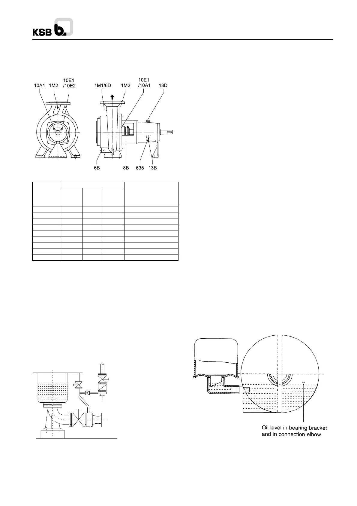
Procedure
Unscrew vent plug. Pour in oil through the vent plug aperture
after removing the reservoir of the constant level oiler, until oil
appears in the vertical portion of the connection elbow of the
constant level oiler (see Fig. 6)
Then fill the reservoir of the constant level oiler with oil and fit
it back into operating position. Screw vent plug in again. After
a short time has elapsed, check whether the oil level in the
reservoir has sunk. The reservoir should always remain filled.
If the vent plug is inaccessible or difficult to reach e.g. the oil
can be filled into the bearing bracket through the connection
elbow of the constant level oiler.
Fig 6 : Oil fill
CAUTION:
The oil level should always be situated below the level of the vent
slot arranged at the top edge of the connection elbow and this slot
should always be perfectly dry. Do not tighten the elbow by applying
the force on the reservoir. Use lock nut for this purpose.
Pump Sizes
65 - 200 100 - 400
Connections 125 - 500 Designation
150 - 315
1 M .1 / 6D G 1/2" G 1" G 1" Pressure guage / venting
1 M .2 G 1/2" G 1/2" G 1/2" Pressure guage
6 B G 3/4" G 3/4" G 1" Casing drain
8 B G 1/2" G 1/2" G 1/2" Leakage drain
10 E .1 G 1/4" G 1/4" G 3/8" Sealing liquid inlet
10 A .1 G 1/4" G 1/4" G 3/8" Sealing liquid outlet
13 B G 1/4" G 1/4" G 1/4" Oil drain
13 D 20 Ø 20 Ø 20 Ø Vent Plug
638 G 1/4" G 1/4" G 1/4" Constant level oiler
65 - 315
80 - 250
Z
A
V
R
E
B
C
A Main isolating line
B Vacuum balancing line
C Isolating valve
E Vacuum tight isolating valve
R Check valve
V Vessel under vacuum
Z Intermediate flange
2

 Loading...