KWP
7. Unscrew the impeller screw 906 (right hand thread),
remove the O Ring 412.03. Pull off the impeller with a special
puller type device of KSB make as shown in fig.9. Remove
the key.
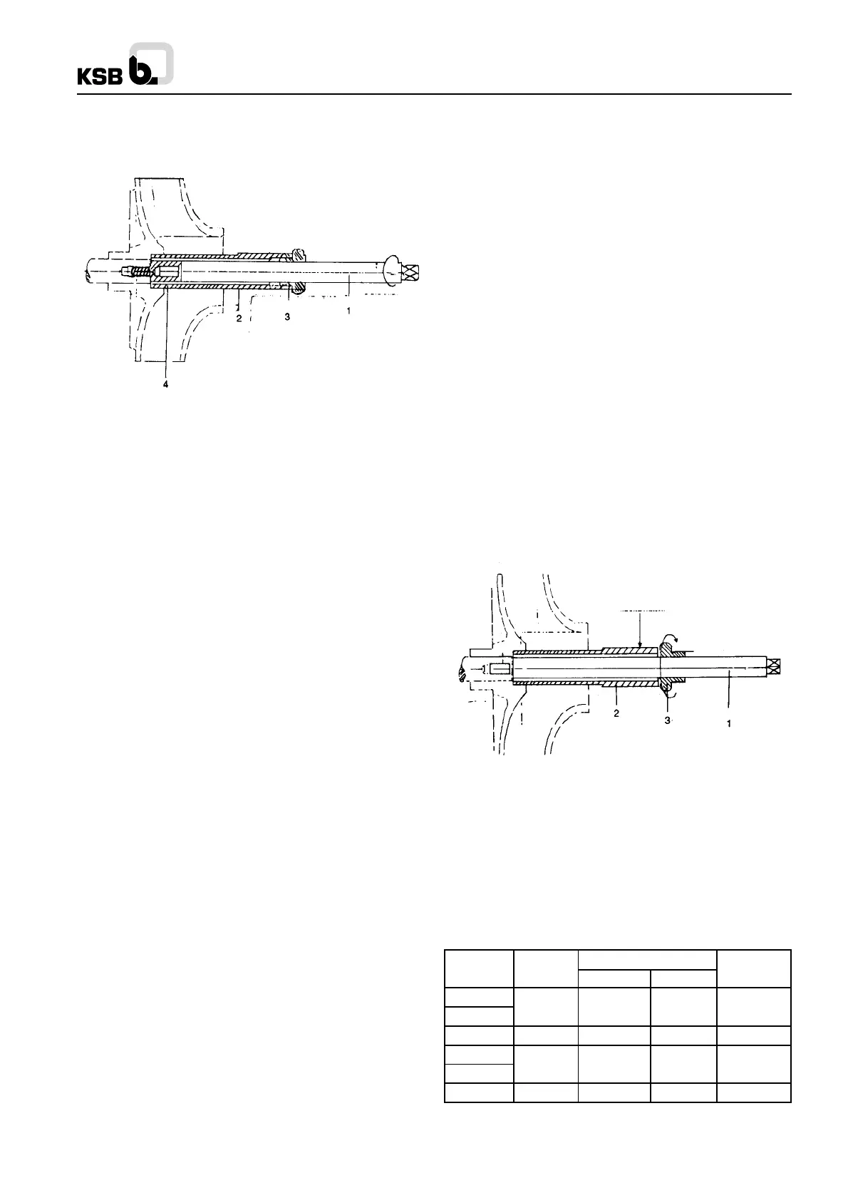
1. Spindle
2. Puller/Pusher bolt
3. Nut
4. Extension piece
Fig no. 9 Arrangement of Puller
8. Dismantling the shaft seal : Remove the stuffing box gland
452 after unscrewing the hexagonal nuts 920.2. Strip off the
stuffing box pressure ring 454, the packing rings 461, lantern
ring 458 and the packing rings located behind the lantern ring.
9. Remove pressure cover 163 from the bearing bracket
lantern.
10. Unscrew nuts 920.4 on the connecting studs of the flange
between bearing bracket lantern and bearing bracket , and
remove the bearing bracket lantern 344.
11. Pull shaft protection sleeve 524.01 together with Flat
Gasket 400.04 off the shaft.
Force open the splash ring 524.01 by splaying it with a wedge
or a screw driver and then pull it off the shaft.
12. Pull off pump half-coupling from stub shaft with the aid
of a puller device.
13. Dismantle pump end and motor end bearing cover 360.1
and 360.2 by unscrewing the screws 914.2/3.
14. Carefully drive out the shaft 210 together with bearings
321.1/2 or 322 towards the motor end.
15. If it is necessary to renew the antifriction bearings 321.1/
2 or 322, they should be warmed up by means of a welding
torch or a blow-lamp before pulling them off the shaft, and
the shaft itself should be kept as cool as possible.
16.Examine wear plate 135.01 for signs of wear and if
necessary remove them from pump casing.
For dismantling the wear plate, remove hex head bolt 901.03
together with gasket 411.13. Take care not to damage gasket
411.1 and O ring 412.05
17. Clean all components and inspect them for signs of wear.
Touch up any damaged parts or replace them by new ones.
5.1.3. Reassembly
Reassembly proceeds in reverse sequence to dismantling. It
should be undertaken with the greatest care, and with the aid
of the relevant sectional drawing, to ensure trouble-free
running of the pump.
Carefully examine all seals during reassembly O-rings, radial
seal rings and gaskets should be examined for any sign of
damage and if necessary replaced by new ones. Flat gaskets
should in principle always be replaced by new ones. The
antifriction bearings, shaft bearing brackets and stuffing box
components should be thoroughly cleaned in petrol or benzol.
Coat the fits of the individual components with graphite or a
similar lubricant before reassembly, this also applies to the
screw threads.
The following points should be carefully observed.
1. Standard bearing arrangement
If new bearings are fitted, make sure that they are of the correct
size and type (see 4.2). Heat bearings in an oil bath to
80
0
C.(175 o F) approx. before slipping them onto the cleaned
shaft, until they abut against the shaft shoulders. Replace shaft
carefully in the bearing bracket.
2. When mounting the bearing covers 360.01/.02 take care not
to damage the gaskets 400.01/.02 and oil seals 421.01/.02.
Press neck ring 456.01 into the pressure cover 163. In the
case of the packing arrangement illustrated in For packing
the stuffing box refer to point No. 3.1.2.6.
For packing the stuffing box refer point No. 3.1.2.3.
CAUTION :
The stuffing box should drip slightly when the pump is running.
Any sealing and flushing liquid connections on your pumps
should be checked from time to time for unimpeded flow of
the fluid. After the gland has been tightened repeatedly in the
course of operation until it can be tightened no further, the
pump should be repacked completely with new packing.
3. Carefully insert the impeller gasket 400.04 and make sure
that all joints and sealing faces are perfectly clean.
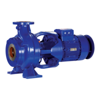
The impeller should be pressed onto the shaft only with the
help of a pusher device supplied by us. Hammering should
never be resorted to. See Fig. 16.
1. Spindle
2. Puller/pusher bolt
3. Nut
Fig. no. 10 : Arrangement of Pusher.
4. After assembly in the pump casing which has remained in
situ in the piping, the coupling alignment should be checked
(see item 1.3)
5. Fill in oil in accordance with item 3.1.
5.2 Bearings
The pump is fitted with antifriction bearings as follows
A. Standard bearing bracket
Table 3
Pump side Drive side
65-200
80-250
65-315 P45-120 6409 6409 500
100-400
150-315
125-500 P65-160d NU 413 6413 1800
150064116411P55-140
Pump size
il fill (cm³)
approx.
Bearing
bracket
P35/80 6307 6307 500
Bearings
6