WK
9. Piping
The main piping should be connected to the pump without
transmitting any stresses or strains onto the latter. Any
appreciable piping forces which are transmited to the base-
plate via the PUMP can detrimentally affect the alignment and
the running of the pump. Such forces should therefore be kept
to a minimum at all costs.
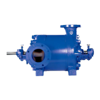
9.1 Suction Lift Line and Positive Suction Head Line
The pipe line connected to the suction casing (106) is called
either a suction lift line or a (positive) suction head line,
depending on whether the pressure at the pump inlet is below
or above atmospheric pressure. This line should be kept as
short as possible. (see Figs. 43 and 44)
Suction lift lines should rise all the way towards the pump,
they should also be absolutely leak tight and be laid in such a
way as to prevent the formation of air pockets at any point.
(see Fig. 43).
Fig. 43 Suction lift line
The nominal size of the pump suction flange is no accurate
guide to the size of the suction lift line. The latter should be
sized, as a first approximation to give a velocity of 2m/sec.
approx. In principle, every pump should be equipped with its
own individual suction lift line. If this is not feasible for particular
reasons, the common suction lift line should be sized for a s
low a velocity as possible and preferably for a constant velocity
right up to the last pump on the line (see Fig. 45).
In addition, pumps connected to a common suction lift line
should be equipped with VSM stuffing boxes.
If the suction lift line is buried, it should be hydrostatically tested
at 3 to 4 bar before burial.
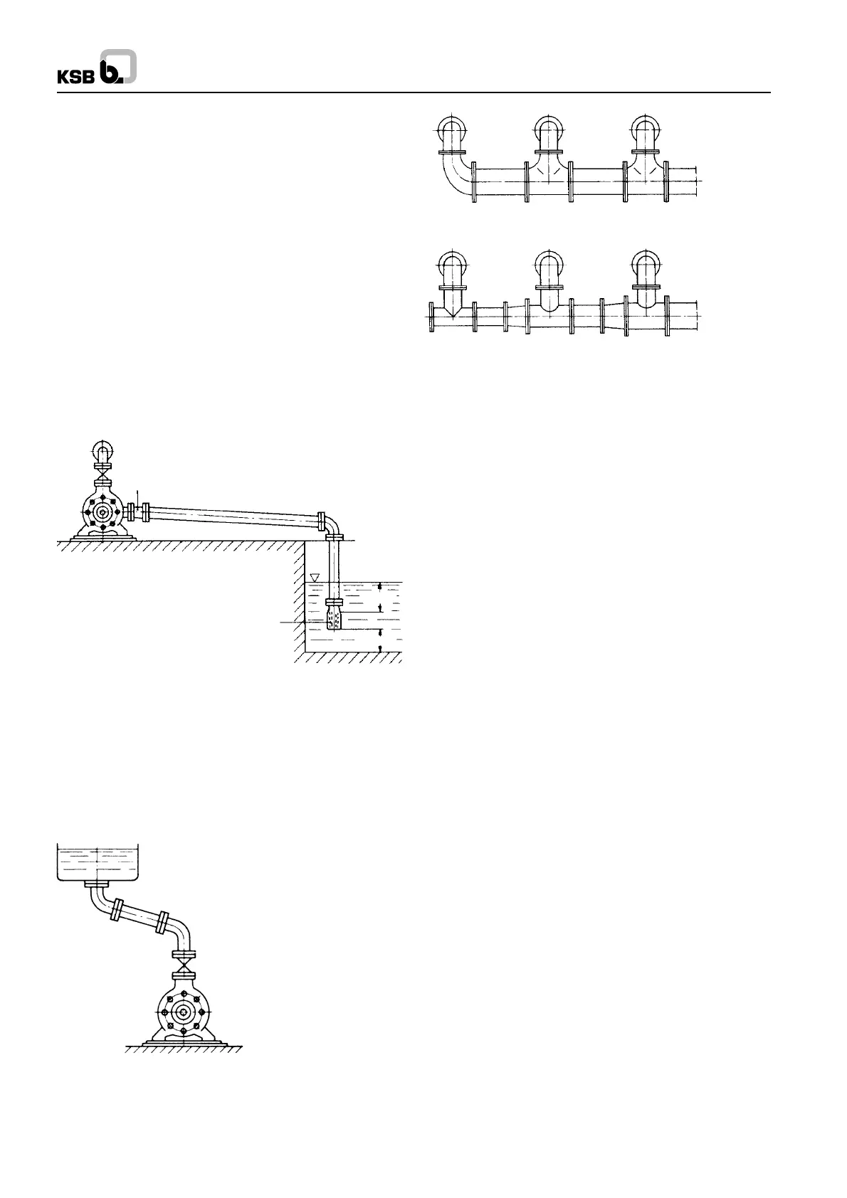
The same remarks as above apply to the nature and laying of
(positive) suction head lines. Horizontal lenngths of suction
head lines should however be laid with a slightly rising slope
towards the suction vessel. If it is not feasible to avoid apexes
in the suction head line, each apex should be equipped with a
vent cock. It is also advisable to avoid any appreciable length
of horizontal suction head line laid close beneath the suction
vessel because of the danger of evaporation (see Fig. 44).
9.1.1 Strainers in Suction Head Line/Suction Lift Line
Before a new pumping installation is commissioned, all the
vessels, piping and connections should be thoroughly cleaned,
flushed through and blown though. It often happens that welding
beads, pipe scal and other dirt only become detached from
inside the piping after a considerable period of service; they
must therefore be prevented from penetrating inside the pump
by the provision of a strainer in the suction head or suction lift
line. This strainer should have a free area of holes equal to 3
times the pipe cross section area approx., in order to avoid an
excessive pressure drop when foreign bodies tend to clog the
strainer.
Conical (hat shaped) strainers have given good results in
service (see DIN 4189), they should have a woven wire insert
of corrosion-resistant material with a 1.0 mm. mesh width of
0.5 mm. diameter wire. The fine strainer should precede the
coarse strainer in respect of direction of flow of the fluid. During
the initial period of commissioning, the suction pressure should
be kept under frequent observation. If the NPSH available is
found to decrease, this may be due to clogged strainers (the
pressure drop acros the strainer should be measured with the
aid of a differential pressure gauge). The strainers should then
be cleaned. (see Figs. 46 and 47).
Unless anything to the contrary has been specified, the max.
permissible pressure drop across the strainer should not
exceed 3 meters.
Eccentric reducer (fitted belly down)
Suction strainer basket
>0.5m
>0.5m
Fig. 44 Suction head line
Fig. 45 Common suction lift line for several pumps
Correct
Wrong
11
 Loading...


