WK
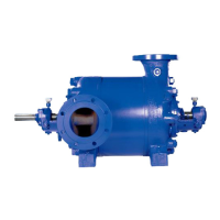
Fig. 4 Dismantled rotor
In order to balance the axial thrust, throttling passages are
arranged at the impeller necks at the suction and discharge
end of each impeller, and additional balancing holes are
provided in the impeller necks at the discharge end
(See Fig. 5).
A fixed bearing absorbs the residual axial thrust generated
and also locates the rotor in the axial position; in the standard
bearing construction, this bearing consists of a deep groove
ball bearing (321) and in the pump construction with heavy
duty bearing bracket, it consists of two angular contact ball
bearings (320).
1.3 Bearing Arrangement
WK pumps are fitted with different types of beaings and bearing
housing, depending on the differential head (generated
pressure) of the pump. In the case of low differential heads,
the standard bearing construction is provided. In the case of
higher total heads, the heavy duty bearing construction is
provided to absorb the increased residual thrust.
The pump manufacturer decides which type of bearing
arrangement shall be provided.
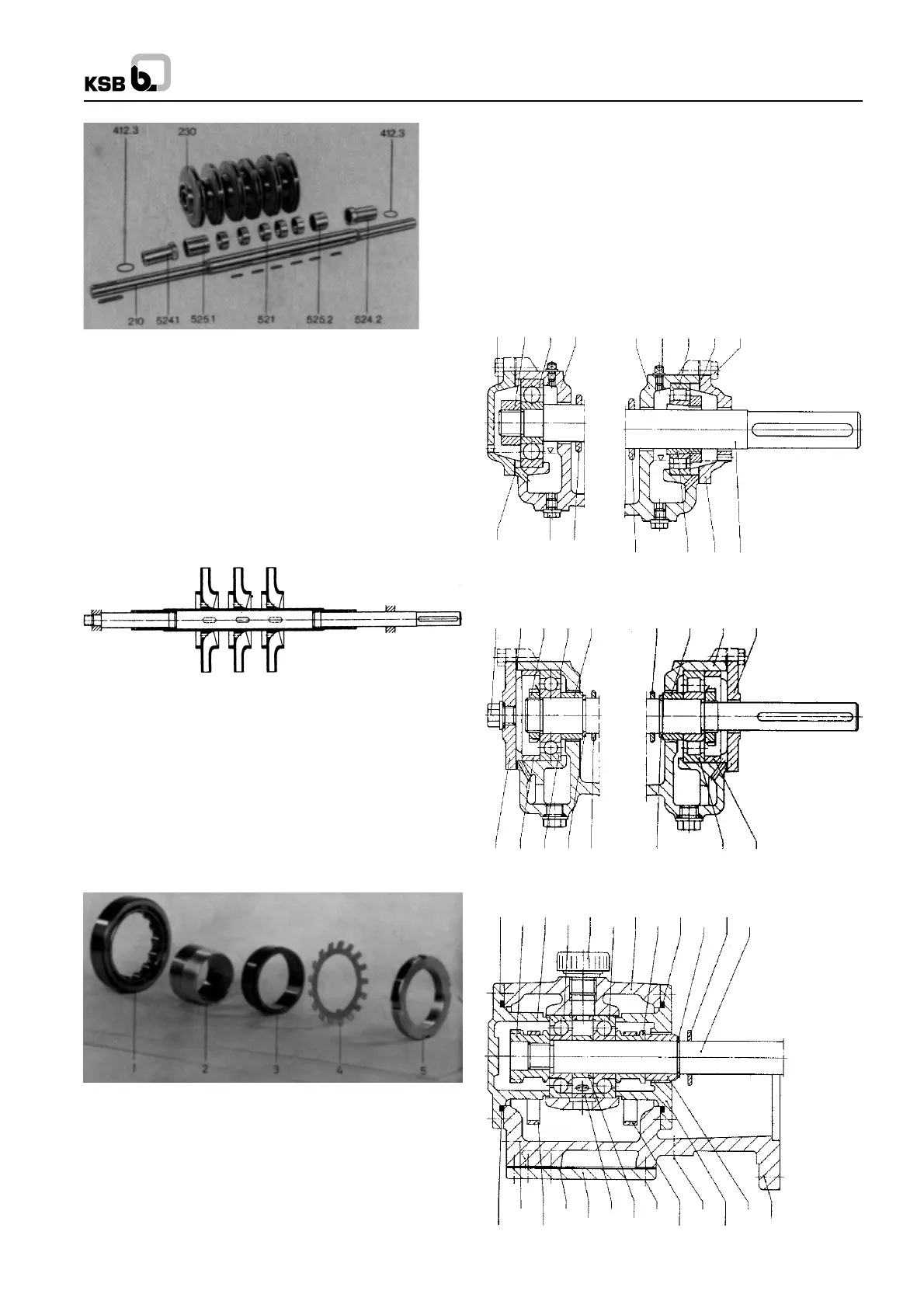
Fig. 6 Individual bearing components (drive end)
Part 1 = Outer race with cage and rollers
Part 2 = Adaptor Sleeve
Part 3 = Inner bearing race
Part 4 = Locking Washer
Part 5 = Withdrawal Nut
Standard Bearing Construction :
Drive end : 1 Cylindrical roller bearing in accordance with DIN
5412 (see Fig. 6) with adaptor sleeve in accordance with DIN
5412 and standard bearing bracket (No adaptor sleeve
provided on pump size 150).
End side : 1 deep groove ball bearing in accordance with DIN
625 and standard bearing housing (see Figs. 7 and 8).
Heavy Duty Bearing Construction :
Drive end : Same as atandard bearing construction. End
side : 2 matched angular contact ball bearings in accordance
with DIN 628; X arrangement and heavy duty bearing bracket
(see Fig. 9).
Fig. 9 Bearing construction with heavy duty bearing
bracket size 150.
Fig. 7 Bearing construction, size 40 to 125
361 920.4 321 350 350 731.2 322 400.4 901.2
400.4
903.4
(13B)
507
507 52-1 360 210
Fig. 8 Bearing construction, size 150
903.12
400.4 920.4 350 525.4
507 525.4 350 360
361 543 321 932 507 932 322 543
Drive end
Fig. 5 Rotor
901.3 361 913 350.2 412.7 507
210
932508320320923
412.7 644 644 360.2
902.3
525.5
720.3
(
8B
)
901.4
525.8160
543400.5
903.5
(
13B
)
2
 Loading...


