WK
bearing (321) by means of loan forcing screws until the
bearing housing and bearing can be pulled off the shaft
without effort.
5. Inspect condition of deep groove ball bearing (321) and if
necessary remove it form bearing housing (350).
6. Strip splash ring (507) off the shaft.
11.2.2.2 Heavy Duty Bearing Construction
1. Remove bearing end cover (361) including O-ring (412.7).
2. Unscrew shaft nut (923) and remove it from the shaft
together with lubricating ring (644).
3. Unscrew hex. nuts (920.2) from studs (920.3) in outlet
cover (107), in order to dismantle bearing housing (350).
4. Force off (with the aid of forcing screws) bearing housing
(350.2) together with angular contact ball bearing (320),
inner distance ring (525.8), outer distance ring (543), guide
bush (508) and lubrication ring (644), and pull the bearing
assembly off the shaft with the aid of an extractor.
5. Remove distance bush (525.5), circlip (932) and splash
ring (507) from the shaft.
6. Inspect condition of angular contact ball bearing (320)
and if necessary remove it form bearing housing (350.2).
11.3 Removing the Shaft Seal
11.3.1 Soft-packed Stuffing Box Construction
1. Pull stuffing box gland (452) off the shaft.
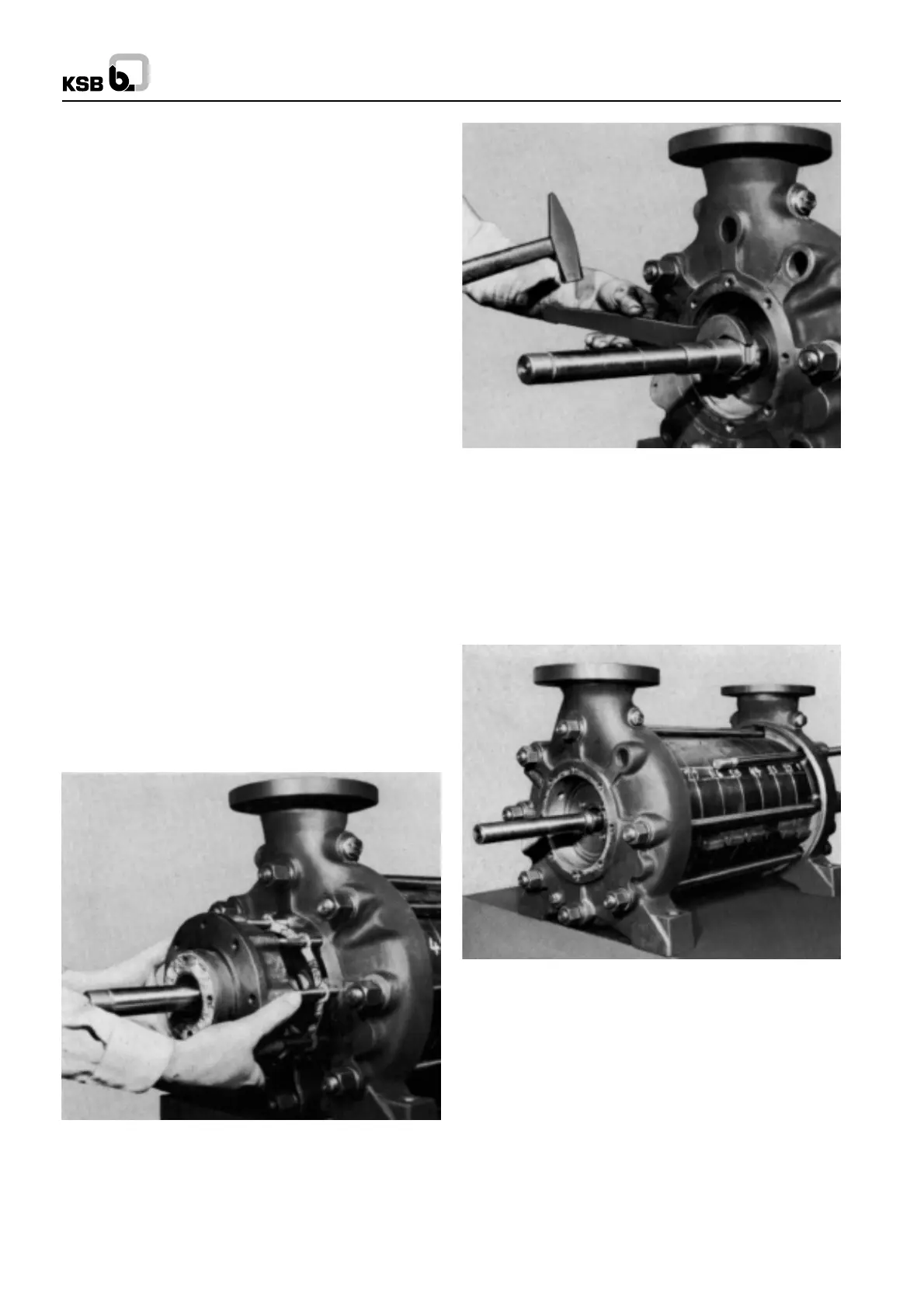
2. Force off and remove stuffing box housing (451). On
pumps equipped with cooled stuffing boxes, force off and
remove the stuffing box housing (451) including cooling
cover (165) (see Fig. 63).
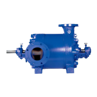
3. Slacken shaft protection sleeve (524.2) and remove it from
shaft (210) (see Fig. 64)
Fig. 63 Removing the stuffing box housing (451)
11.4 Dismantling the Pump Body
1. The stage casings (108) should be numbered
consecutively in respect of their positions in relation to
one another before dismantling, to ensure that the suction
casing (106), the stage casing (108) and the discharge
casing (107) are all reassembled in the correct sequence
in relation to one another during reassembly (see Fig.
68).
Fig. 64 Slackening shaft protection sleeve (524.2)
2. Unscrew nuts (920.1) at discharge end or connection rods
(905) and pull the connection rods out of the suction and
discharge casing (see Fig. 68).
3. Underpin the pump at the stage casing (108) with wooden
blocks or an erection trestle, so as to free the component
which is to be dismanntled next.
4. Force discharge casing (107) together with diffuser/last
stage (171.2) off stage casing (108) and lift it off (see Fig.
69 and 70).
Fig. 68 Identification of casing components and removal of
tie rods
17
 Loading...


