WK
A newly packed stuffing box should leak profusely at first. If
this leakage does not cease of its own accord after a relatively
short period of operation, the nuts on the gland should be
tightened slowly and evenly while the pump is running, until
the stuffing box only drips tightened evenly and not askew, as
otherwise the shaft protection sleeves (524.1/.2) might be
damaged (see Fig. 23).
The leakage rate in service of a soft-packed stuffing box should
amount to 3 to 5 litres/hours approx.
If the newly packed stuffing boxes start to smoke when the
pump is started up for the first time, the pump should be
switched off. If the smoking persists after the pump has been
started up again and operated several times in succession,
the nuts on the gland should be slackened slightly, or the stuffing
box should be inspected if necessary.
1.5.1.3 Packing Material
When selecting the packing material, make sure it is compatible
with the fluid pumped (consult the manufacturer in case of
doubt).
In steam generating plants, the asbestos-graphite packing
material specially developed for hot water service has given
good results. Packing material which has been dept in store
for a certain period has a longer service life than packing
material fresh from the packing manufacturer.
1.5.2 Mechanical Seals
Mechanical seals can be fitted as shaft seals in lieu of soft-
packed stuffing boxes. If it is intended to replace soft-packed
stuffing boxes by mechanical seals after the pump has been
in service for some time, it is necessary for the pump to be
equipped with stuffing box holdings (451) for ‘‘V’’ special stuffing
boxes. It is also necessary to re-machine two tapped holes in
the cooling cover (165) for the attachment of the seal cover
(471).
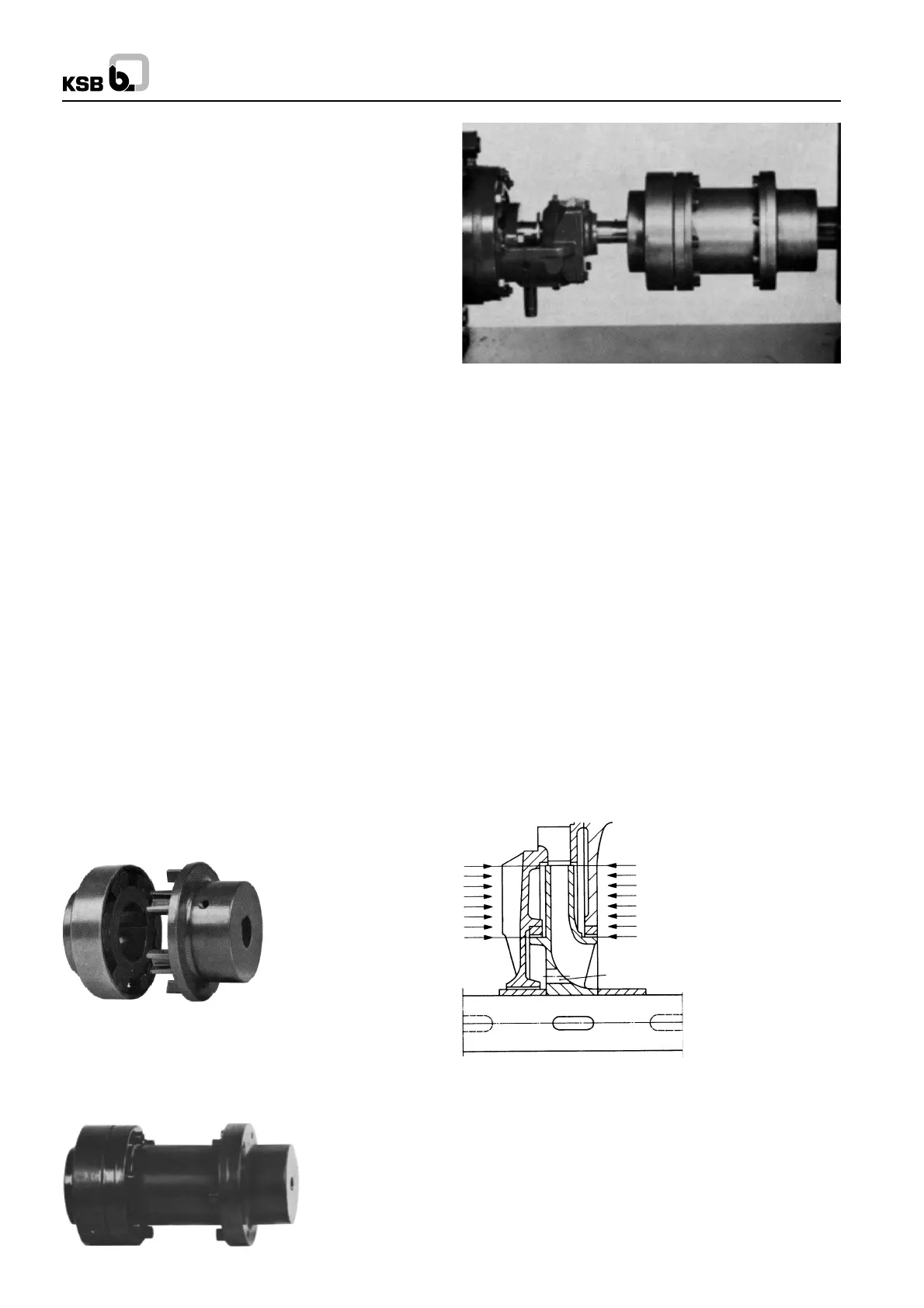
1.6 Coupling
The pump on connected to the driver by a flexible coupling.
Fig. 29 illustrated the type of coupling most frequently used.
Fig. 29 Flexible coupling
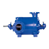
Spacer type couplings (see Figs. 30 and 31) enable inspections
and minor repairs (e.g. the fitting of new bearings or shaft
protecting sleeves) to be carried out without removing the driver.
Fig. 30 Spacer type flexible coupling
Fig. 31 Mounted spacer-type flexible coupling
2. Mode of Operation of Pump
The fluid flows through the suction casing towards the impeller
at a given pressure. Energy is transmitted to the fluid by the
impeller, which is fitted with vanes. From the impeller, the fluid
flows into the diffuser, where kinetic energy is converted into
potential energy, increasing the pressure rise still further.
The return guide vanes arranged on the discharge end cheek
of the diffuser (171.1) guide the fluid under hydraulically
favourable conditions towards the eye of the following stage
impeller (230). This process is repeated from one stage to the
next, and the pressure rise by the same amount in each stage,
viz. by the stage generated pressure. After leaving the final
stage diffuser (171.2), the fluid flows through the discharge
casing (107) into the discharge line connected to this casing.
The generated pressure creates an axial thrust on the pump
rotor of single and multistage centrifugal pumps. By the
provision of narrow throttling gap between the impeller necks
and the casing wearing rings at either side of each impeller,
equal size lateral impeller space, and therefore almost identical
pressure conditions are created at the suction and discharge
ends of each impeller (see Fig. 34).
The balance holes in the discharge side impeller cheeks ensure
a compensation of pressures between the suction and
discharge sides of the impellers in the region situated between
the impeller hub and the throttling gap, thus again preventing
the creation of any appreciable axial thrust in this region of the
impeller. Any residual axial thrust is absorbed by the fixed
bearing in the discharge end bearing housing. This fixed
bearing also locates the axial rotor position.
Fig. 34 Axial forces acting on impeller
Balance hole
7
 Loading...


