WK
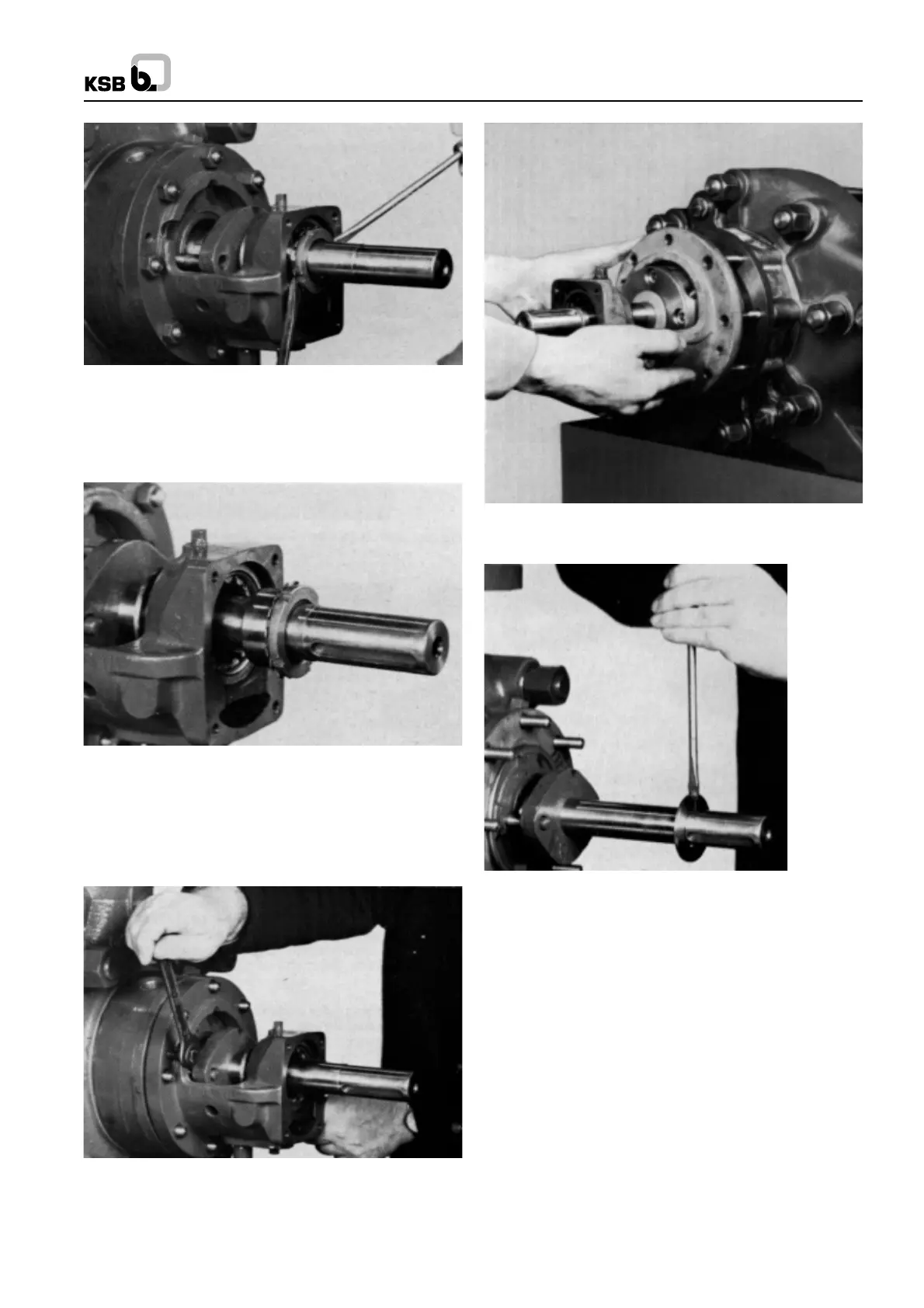
6. Pull out inner race of cylindrical roller bearing (322)
together with adaptor sleeve (52.1) from bearing housing
(350) (see Figs. 58 and 59)
Fig. 58 Forcing out the inner components of the cylindrical
roller bearing
7. Unscrew and remove hex. nuts (920.2) from studs bolts
(902.1) in the suction casing (106) in order to dismantle
the bearing housing and stuffing box housing (see Figs.
60 and 61).
Fig. 59 Dismantled inner components of cylindrical roller
bearing
Fig. 60 Forcing off the bearing housing
Fig. 61 Removing the bearing housing (350) together with
outer race of cylindrical roller bearing (322)
8. On pump size 150 which is fitted with a cylindrical roller
bearing without adaptor sleeve, the bearing housing (350),
including the outer race of the bearing and the other
distance ring (543) are removed after unscrewing the hex.
nuts (920.4), then the inner race of the bearing and the
inner distance ring (525.4) are pulled off the shaft, and
the circlip (932) removed.
11.2.2 Dismantling the End side Bearing
11.2.2.1 Standard Bearing Construction
1. Remove bearing end cover (361) together with gasket
(400.4).
2. Unscrew hex. shaft nut (920.4) and remove it from the
shaft.
3. Unscrew and remove hex. nuts (920.2) from studs (902.1)
in discharge casing (107), in order to dismantle the bearing
housing and stuffing box housing.
4. Force off bearing housing together with deep groove ball
Fig. 62 Stripping off the splash ring
16
 Loading...


