2.1.3 Barrier to Habitable Rooms
A E8KT/E10KT/E12KT installed in any corridor, hallway, lobby or the like and leading to an
emergency exit shall ensure sufficient clearance for safe egress of at least 1 meter.
The E8KT/E10KT/E12KT must also not be installed in potentially explosive atmospheres for
gas cylinders that are heavier than air gases and have a vent clamp in accordance with AS /
NZS 3000.
To protect against the spread of fire in living spaces where the E8KT/E10KT/E12KT is
mounted or on surfaces of a wall or structure in living spaces with a E8KT/E10KT/E12KT on
the other side, the wall or structure shall have a suitable non-combustible barrier. If the
mounting surface itself is not made of a suitable non-combustible material, a non-combustible
barrier can be placed between the E8KT/E10KT/E12KT and the surface of a wall or structure.
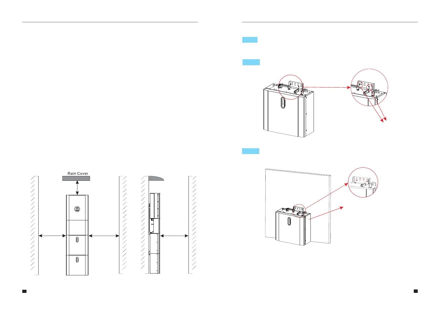
If the E8KT/E10KT/E12KT is mounted at a wall or at a distance of 300mm from the wall or the
structure separating it from the habitable space, the distances to other structures or objects
must be increased. The following distances must remain free:
(i) 600 mm beside the E8KT/E10KT/E12KT;
(ii) 500 mm above the E8KT/E10KT/E12KT;
(iii) 600 mm before the E8KT/E10KT/E12KT.
If the distance between the E8KT/E10KT/E12KT and the ceiling or any object above the
system is less than 500mm, the ceiling or structural surface above the system must be
made of noncombustible material within a radius of 600mm around the system.
The E8KT/E10KT/E12KT must be mounted to ensure the highest point is not more than
2.2m above the ground or the platform.
Step 1 Remove the battery and inverter from the packaging box.
19
20
Figure 8 Limited Distance of Installation to Neighboring Objects
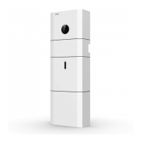
Step 2 Assemble the battery mounting panel on the battery.
Figure 10 Assemble Battery Mounting Panel
M5*12 Screws
2.2.1 Battery Installation
2.2 Installation
Step 3
Position the battery parallell to the wall and use a Φ10mm drill to drill holes at a
depth of about 70mm in the wall for subsequent fixation of the mounting plates.
Debris Baffle, drill φ10,
depth about 70 mm
Figure 11 Battery Installation -
Drill Holes
≥600mm≥600mm
≥500mm
≥600mm
Top----------- 500mm
Front--------- 600mm
Laterals------600mm
User Manual User Manual
Note: A shelter must be installed above the SINERGY