CONFIDENTIAL - This document is the property of K.T.C. S.r.l. and cannot be reproduced or issued to third parties without written
authorization. K.T.C. S.r.l. shall safeguard its rights to the full extent of the law.
OPERATION AND INSTALLATION MANUAL
COD. 091114 – COMPACK 2 ECO / SPECIAL - REV. 08 - DATE 10/2020 page 15 of 63
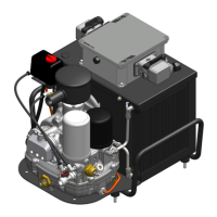
4.2 OPERATING PRINCIPLE
During the initial phase (unload), the electric motor ref. 29 reach the set operating RPM.
The solenoid valve is not powered and thus the suction valve ref. 1 remains closed. The
length of this phase can be set.
During the second phase (load), the solenoid valve is powered and the suction valve ref. 1 is
opened, thus allowing air to pass through the suction filter ref. 16 and enter the screw
compressor ref. 2. This starts the compression phase.
The air/oil mixture delivered by the screw compressor ref. 2 is conveyed into the air/oil
separator tank ref. 15.
An initial portion of the oil is separated from the air mechanically and deposits at the bottom
of the tank while the air collects at the top.
By force of pressure the air is forced to flow through the oil separator filter ref. 13 and, after
further separation of the oil, it is sent on to the minimum pressure valve ref. 9. This allows
passage of the air only after the pressure set point has been reached. When this happens, the
air passes through the air tank ref. 3 (if present).
The oil removed from the air inside the oil separator filter is sent, through the oil return from
separator line ref. 12, into the screw compressor. The amount of oil can be monitored
through oil recovery window ref. 22.
The pressure sends oil at the bottom of the tank to the thermostatic valve ref. 25. This valve
sends the oil with a temperature above the set point to the oil radiator ref. 7 where it is
cooled. Once cooled, the oil returns to the thermostatic valve, is mixed with hot oil coming
from the tank and is again checked by the thermostatic valve. Once the temperature set point
(low) is exceeded, the oil is sent to the oil filter ref. 17 and then into the screw compressor.
When the set maximum working pressure is reached, the pressure switch ref. 11 remove
power from the solenoid valve and trips the circuit. The suction valve ref. 1 closes air flow
and the compressor enters in "unload" operating mode. This situation remains in force until
the system minimum pressure setting is reached.
If consumption is low or has stopped unit will continue operate in no-load mode for a set
amount of time and then reverts to stand-by mode.
The condensate that accumulates inside the tank must be discharged daily through the
special drain in the lower part of the tank.