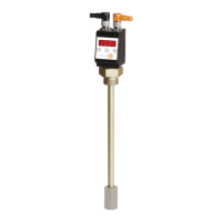
The level switches series NVT-E serve for monitoring level and temperature in tanks in fluid systems.
Depending on the model, the level switches are equipped with a different number of switching outputs.
Please find the configuration on the type plate. Here you will find our type description.
1 Technical data 4
2 Advice 5
2.1 General advice 5
2.2 Safety and advice symbols 5
2.3 General hazard warnings 5
2.4 Intended use 5
3 Assembly 6
3.1 Start-up (General) 6
4 Operation 6
4.1 Switching on 6
4.2 LED status display 7
4.3 Button functions 7
4.4 Button lock active 8
4.5 Summary of menu 8
4.6 Amendment of basic settings 9
4.6.1 Defining filling level 10
4.6.2 Defining temperature 10
4.6.3 Reassignment of switching outputs 11
4.6.4 Setting updating rate of display 11
4.6.5 Activating/Deactivating button lock 12
4.6.6 Scaling of charging level 12
4.6.7 Maximum displayed value of filling level 13
4.6.8 Minimum displayed value of filling level 13
4.6.9 Resetting factory settings (Reset) 13
4.6.10 Factory settings 14
4.7 Switching outputs 15
4.7.1 Definition of switching characteristics 15
4.7.2 Upper switching limit (set point) 17
4.7.3 Lower switching limit (reset point) 17
4.7.4 Delay for set point 18
4.7.5 Delay for reset point 18
4.7.6 Testing the switching output 19
4.7.7 Changing display function of status LED 19
4.8 Analogue outputs 21
4.8.1 Assignment of upper limit 21
4.8.2 Assignment of lower limit 21
4.8.3 Defining the type of signal 21
4.8.4 Testing the analogue output 22