NVT-E
Operating/Assembly instructions
Please observe protection
note ISO 16016.
The level transmitters are supplied fully assembled and can be fixed to the tank by means of the screw-in thread.
Please make sure that the float can move freely and sufficient distance to the tank walls and to other equipment is
kept. If the float has possibly been disassembled it has to be made sure that the magnet inside the float is located
above the fluid level. This can easily be inspected by means of a piece of iron which allows to find out the position
of the magnet inside the float.
The electrical connection may be performed by trained technical staff only.
Connection
The mains voltage is connected to connector S6 or M12, respectively. Nominal voltage of devices is 24 V DC.
For mounting dimensions and pin assignment please refer to chapter 1 Technical Data.
The switching outputs are designed as PNP transistor outputs
(see illustration 2).
If the switching output is measured with high-impedance
measuring equipment or if the frequency output is used,
connect a 10 k resistor between output and ground to
avoid faulty measurements.
If an error message appears in the display during normal operation, please
refer to chapter 5 Breakdowns, Causes and Elimination.
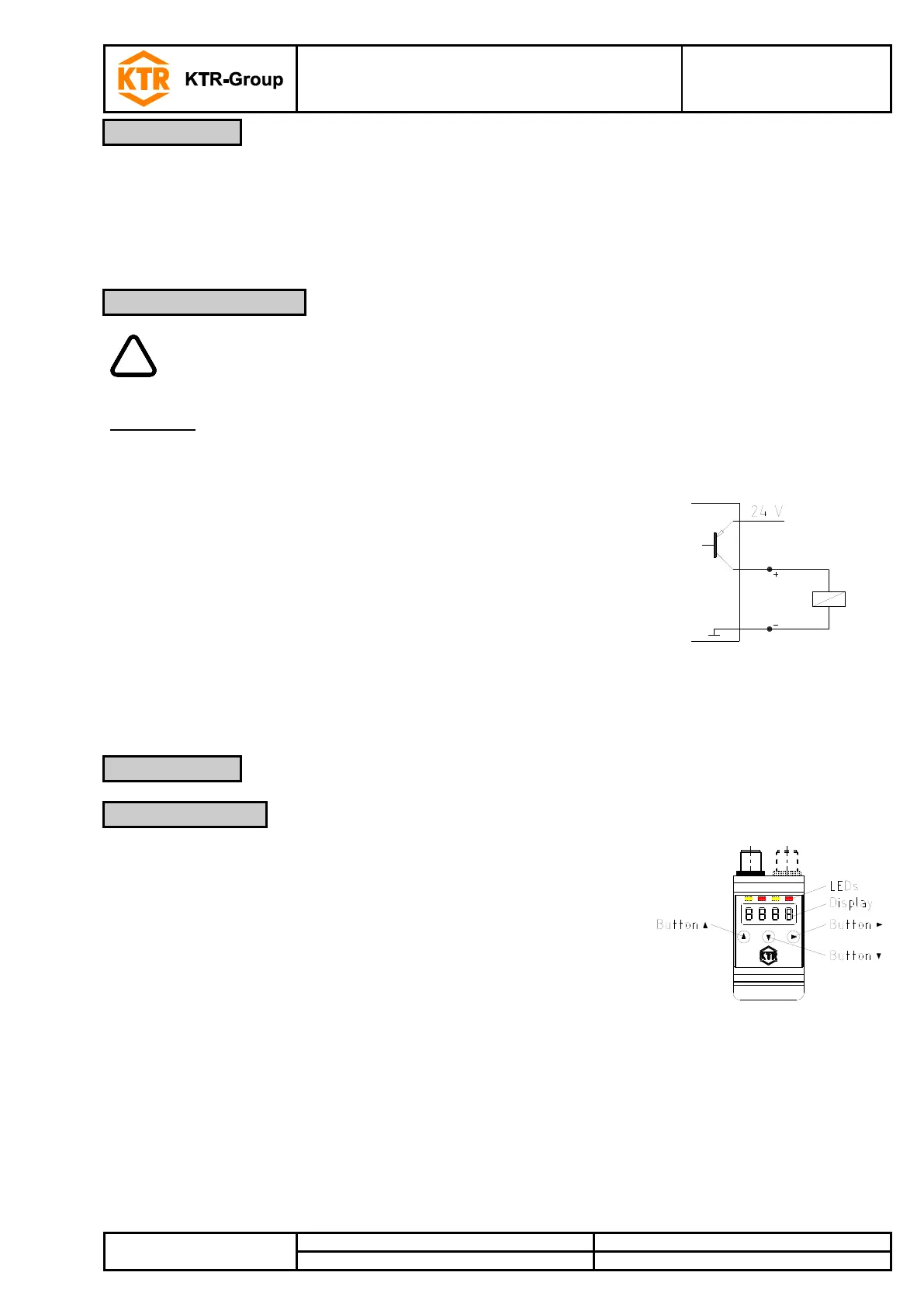
After connecting the device to the mains, the software version is displayed
initially for a short time. Afterwards, the display switches to measurement
display.
The functions of the display and control unit are explained in the following
chapters.