NVT-E
Operating/Assembly instructions
Please observe protection
note ISO 16016.
Light emitting diodes above the measurement display indicate the status of the switch outputs. The LEDs are
assigned to the switching outputs.
Table 2 shows the factory settings for the assignment of the switch outputs as level or
temperature output.
Table 2: LED status display
LED 1 - yellow
indicates switching output 1
LED 2 - red
indicates switching output 2
LED 3 - yellow
indicates switching output 3
LED 4 - red
indicates switching output 4
The switching characteristics of the LEDs (illuminated with closed or opened switch
contact) can be changed, please note chapter 4.7 switching outputs.
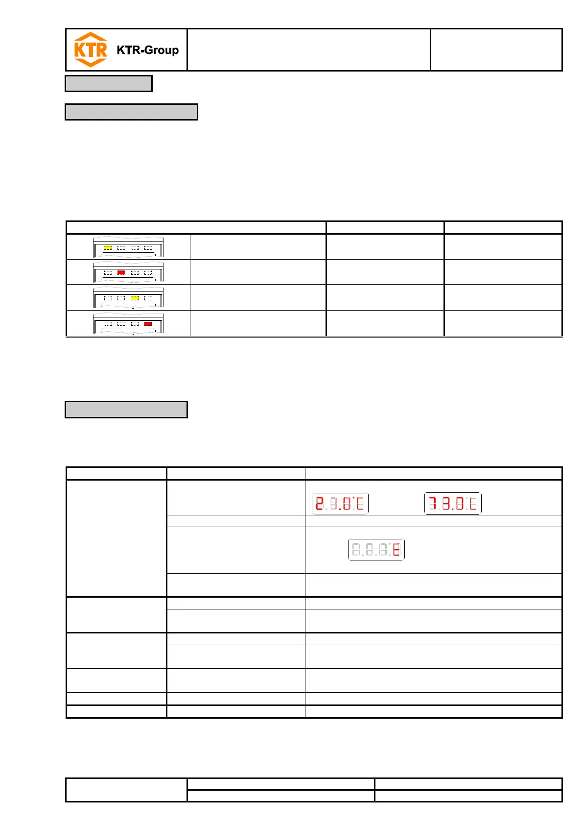
Operation is performed via the buttons below the display.
Table 3: Button functions
Switching the display (example):
- At the end of the menu:
Switching to a superordinate menu
(Exit) indicates the end of the menu
Accepting and saving a value entered or a feature
selection
Displaying the configuration
Scrolling up the menu item, value or feature selection.
Pressing the button changes the value continuously.
Switching to the main menu
Scrolling down the menu item, value or feature selection.
Pressing the button changes the value continuously.
Exiting the main, sub- or optional menu and returning to
measurement display
Switching to the superior menu level
Exiting the main, sub- or optional menu
* The values that were modified are not stored if you exit the optional or setting menu.
A detailed explanation of the menu control is listed in the following chapters.