ELECTRICAL SYSTEM
B1830,B2230,B2530,B3030, WSM
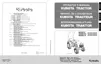
9-S23
3) Head Light Switch Continuity when Setting Switch at "LOW
BEAM" and "HIGH BEAM" Position
1. Set the light switch to the LOW BEAM position.
2. Measure the resistance with an ohmmeter across the B1
terminal (3) to the T terminal (6) and the B1 terminal (3) to the 1
terminal (7).
3. If 0 Ω is not indicated, the head light switch is faulty.
4. Set the light switch to HIGH BEAM position.
5. Measure the resistance with an ohmmeter across the B1
terminal (3) to the T terminal (6) and the B1 terminal (3) to the 2
terminal (2).
6. If 0 Ω is not indicated, the head light switch is faulty.
9Y1210003ELS0029US0
4) Turn Signal Light Switch Continuity When Setting Switch
Knob "OFF" Position
1. Set the turn signal light switch to the OFF position.
2. Measure the resistance with an ohmmeter across the B2
terminal (4) and L terminal (9), and across B2 terminal (4) and
R terminal (8).
3. If infinity is not indicated, the combination switch is faulty.
9Y1210003ELS0030US0
Resistance
(Switch at HIGH
BEAM position)
B1 terminal – T terminal
0 Ω
B1 terminal – 2 terminal
(1) Combination Switch
(2) 2 Terminal
(3) B1 Terminal
(4) B2 Terminal
(5) B3 Terminal
(6) T Terminal
(7) 1 Terminal
(8) R Terminal
(9) L Terminal
(10) H Terminal
(A) Head Light "OFF" Position
(B) Head Light "LOW BEAM"
Position
(C) Head Light "HIGH BEAM"
Position
Resistance
(Switch knob at OFF
position)
B2 terminal – L terminal
Infinity
B2 terminal – R terminal
(1) Combination Switch
(2) 2 Terminal
(3) B1 Terminal
(4) B2 Terminal
(5) B3 Terminal
(6) T Terminal
(7) 1 Terminal
(8) R Terminal
(9) L Terminal
(10) H Terminal
(A) Turn Signal Light Switch "OFF"
Position
 Loading...